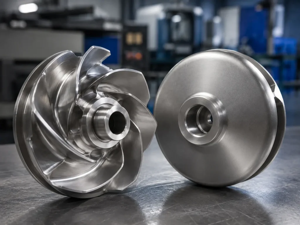
A backward curved motorized impeller is a backward-curved centrifugal fan wheel configured to work directly with a motor, rotor, drive assembly, or compact plug-fan arrangement. The term often describes the complete rotating air-moving module, but an RFQ must separate the impeller itself from the motor, shaft, rotor, inlet cone, housing, electronics, and final fan-performance responsibility.
For custom impeller manufacturing, buyers should provide the approved wheel geometry, motor or shaft interface, hub and bore dimensions, operating speed, rotation direction, material, runout, balancing requirement, and assembly condition. Matson can review selected backward-curved impeller hardware from drawings, 3D files, or samples. This does not mean Matson supplies the motor or validates the complete motorized fan system unless that scope is separately confirmed.
[Image placeholder: Add a real inspection image of a backward curved fan impeller beside its motor or rotor interface drawing, showing the curved blades, inlet ring, backplate, hub, bore, mounting face, runout gauge, and balance report. Alt text: “Backward curved motorized impeller hub interface and balancing inspection”]
Define What “Motorized Impeller” Includes
The first RFQ question is scope. Some buyers use “motorized impeller” for a complete plug fan with motor and controls. Others mean only a backward-curved wheel designed to mount directly on a motor shaft or external-rotor assembly.
| Requested scope | Information required | Responsibility to confirm |
|---|---|---|
| Bare backward-curved wheel | Wheel drawing, hub, bore, rotation, material, speed, runout, and balance. | Impeller manufacturing and inspection only. |
| Wheel with mounting hardware | Keys, bushings, taper lock, fasteners, pilot, flange, or rotor interface. | Fit, supplied hardware, assembly method, and balance condition. |
| Wheel mounted to buyer’s motor or rotor | Motor drawing, shaft or rotor tolerances, assembly procedure, and test requirement. | Who supplies, assembles, tests, and approves the rotating unit. |
| Complete motorized fan module | Motor, controls, inlet cone, housing, guards, airflow duty, electrical standards, and certification. | Do not assume an impeller manufacturer owns the complete system scope. |
Writing “motorized impeller” on the purchase order without this split creates avoidable disputes. The buyer may expect a tested fan module while the supplier quotes only a wheel.
Backward-Curved Geometry Still Belongs to the Approved Fan Design
Backward-curved blades lean away from the direction of rotation at the outlet. The wheel may use single-thickness curved blades, airfoil blades, a front ring, a backplate, a shroud, or another approved construction.
The motorized arrangement does not give the manufacturer permission to alter:
- Wheel outside diameter and axial width
- Inlet diameter and inlet-ring profile
- Blade count, curvature, angle, thickness, and spacing
- Blade inlet and outlet positions
- Backplate or shroud geometry
- Hub position and shaft-axis relationship
- Rotation direction
- Tip relationship to the inlet cone or housing
Final airflow, pressure, efficiency, sound, motor load, speed range, and system curve remain with the fan OEM or responsible engineer. Matson’s backward curved impeller article covers the core blade and wheel geometry in more detail.
The Motor Interface Is a Critical Dimension Set
An accurate wheel can still fail installation if the hub interface is wrong. Buyers should provide the complete motor or rotor connection, not only the bore diameter.
Confirm:
- Straight, tapered, splined, threaded, clamped, bolted, or external-rotor connection
- Bore diameter, tolerance, length, roundness, and surface finish
- Shaft diameter, tolerance, keyway, shoulder, thread, and end condition
- Hub diameter, height, mounting face, pilot, flange, and bolt circle
- Key, bushing, locking device, washer, nut, and fastener requirements
- Axial position relative to the inlet cone and housing
- Permitted face and radial runout
- Assembly temperature or interference method when relevant
- Whether the wheel is balanced alone or with the final hub, rotor, keys, and hardware
If a worn assembly is the reference, inspect the motor shaft and hub together. A scored bore or loose fit can shift the wheel off-axis. Copying that bore may reproduce vibration instead of the original design.
Operating Speed Changes the Manufacturing Review
The RFQ should state normal speed, maximum approved speed, direction, duty cycle, temperature, gas condition, and expected starts and stops. Speed affects centrifugal stress, weld and joint review, balance sensitivity, permissible correction, and the need for overspeed or assembly testing by the responsible system supplier.
Do not estimate allowable speed from wheel diameter alone. Material, blade form, construction, joint design, hub connection, fatigue duty, and validation history all matter. Matson should manufacture to the approved mechanical specification rather than publish a universal safe-speed chart.
Fabricated and Cast Wheels Need Different Controls
| Construction | Main manufacturing checks | Motorized-assembly concern |
|---|---|---|
| Welded fabricated wheel | Blade cutting and forming, fixture, spacing, weld procedure, distortion, hub alignment, runout, and balance. | Weld and mass variation can become more sensitive at direct-drive speed. |
| Cast wheel | Material, casting route, vane consistency, defects, machining allowance, hub machining, inspection, and balance. | Hub and bore must remain concentric with the approved rotating geometry. |
| Machined wheel | Stock material, datum strategy, blade profile, tool access, surface finish, hub interface, and inspection. | Complex geometry still needs approved model control and balance criteria. |
| Wheel with separate bushing or hub | Mating fits, fasteners, locking, pilot, assembly position, and traceability. | The final assembled condition may differ from bare-wheel balance. |
For a fabricated wheel, welding sequence and fixture design help control backplate dish, blade lean, inlet-ring position, and hub movement. Cosmetic appearance alone does not prove that the wheel is concentric or balanced.
Matson’s impeller manufacturing capabilities include casting, CNC machining, selected fabrication, surface treatment, dimensional inspection, dynamic balancing, and export packing for qualified projects.
Runout and Dynamic Balance Are Not the Same Test
Face or radial runout describes geometric movement relative to the rotation axis. Dynamic balancing addresses mass distribution. A wheel can pass one requirement and fail the other.
The buyer should identify:
- Datum and mounting method used for runout inspection
- Measurement location on hub, backplate, inlet ring, or OD
- Face and radial runout limits
- Balance standard or project acceptance requirement
- Balance grade where applicable
- Service speed and balance-machine setup
- Bare wheel, hub assembly, rotor assembly, or complete rotating unit condition
- Key convention and included hardware
- Permitted correction areas and methods
- Required residual-unbalance report
Balancing a bare wheel and then adding an unbalanced bushing, rotor component, or hardware can change the final result. The purchase specification should state who owns final assembly balance.
See Matson’s blower wheel balancing guide for vibration, correction, sample risk, reporting, and RFQ checks.
Inlet-Cone Position Affects More Than Packaging Fit
Compact plug-fan and motorized arrangements often rely on a defined relationship between the wheel inlet and the inlet cone. Axial overlap, radial gap, concentricity, and wheel position can affect rubbing risk and fan performance.
Provide the inlet-cone drawing or the required assembled relationship. The impeller manufacturer should not infer it from one photograph. If the wheel is moved axially to fit the motor interface, the inlet relationship may also change.
Final fan assembly and airflow validation remain with the equipment owner. The wheel drawing should clearly show which dimensions Matson is expected to manufacture and inspect.
Material and Coating Need System Context
Backward-curved wheels may use carbon steel, stainless steel, aluminum, alloy steel, heat-resistant material, or another approved specification. The choice depends on stress, speed, gas, moisture, corrosion, temperature, dust, abrasion, weight, fabrication route, and certification requirements.
Coating thickness and masking can affect bore fit, mounting faces, fastener seats, hub pilots, and balance. Identify areas that must remain uncoated. If powder coating, painting, passivation, or another treatment occurs after balancing, confirm whether the final wheel needs rechecking.
Do not substitute material or coating because it is readily available. The fan or motorized-module owner should approve changes.
What Buyers Should Send for Quotation
Send a controlled package containing:
- Wheel drawing and 3D model with revision
- Clear scope: bare wheel, hardware, assembled rotor, or full module
- Blade, inlet, backplate, hub, and bore dimensions
- Motor shaft or rotor-interface drawing
- Rotation direction with viewing side
- Normal and maximum approved speed
- Material, welding, machining, coating, and finish requirements
- Runout and dynamic-balancing criteria
- Assembly condition and supplied hardware
- Gas, temperature, dust, corrosion, and duty-cycle information
- Quantity, first-article inspection, documents, marking, and packing
If the project starts from a sample, send both sides, hub and bore close-ups, motor-interface photos, balance corrections, damage, repairs, and the matching motor or shaft dimensions.
Common Questions Buyers Ask
What is a backward curved motorized impeller?
It is a backward-curved centrifugal fan wheel configured for direct connection to a motor, rotor, or compact fan assembly. The term may refer to the wheel or a complete module, so the RFQ must define scope.
Does Matson supply the motor?
Matson primarily reviews custom impeller manufacturing. Motor, electronics, housing, inlet cone, complete assembly, and system testing should not be assumed unless separately confirmed in the quotation.
Can a motorized impeller be balanced as a bare wheel?
It can be balanced in a defined bare-wheel condition, but the buyer must decide whether final balance is required with the hub, bushing, keys, hardware, motor rotor, or complete rotating assembly.
What motor dimensions are needed?
Provide shaft or rotor-interface diameter, fit, length, shoulder, keyway, thread, pilot, flange, bolt pattern, axial position, runout, hardware, and assembly method.
Can Matson reproduce a backward curved motorized impeller from a sample?
Matson can evaluate selected sample-based projects, but bent blades, damaged hub fits, worn bores, previous repairs, coating buildup, and balance corrections must be identified and restored from reliable data.
Need a backward curved motorized impeller wheel manufactured from a drawing or sample? Send Matson the wheel and motor-interface drawings, material, speed, rotation, hub and bore, runout, balancing, coating, quantity, inspection, and assembly requirements through the custom fan impeller quote page.