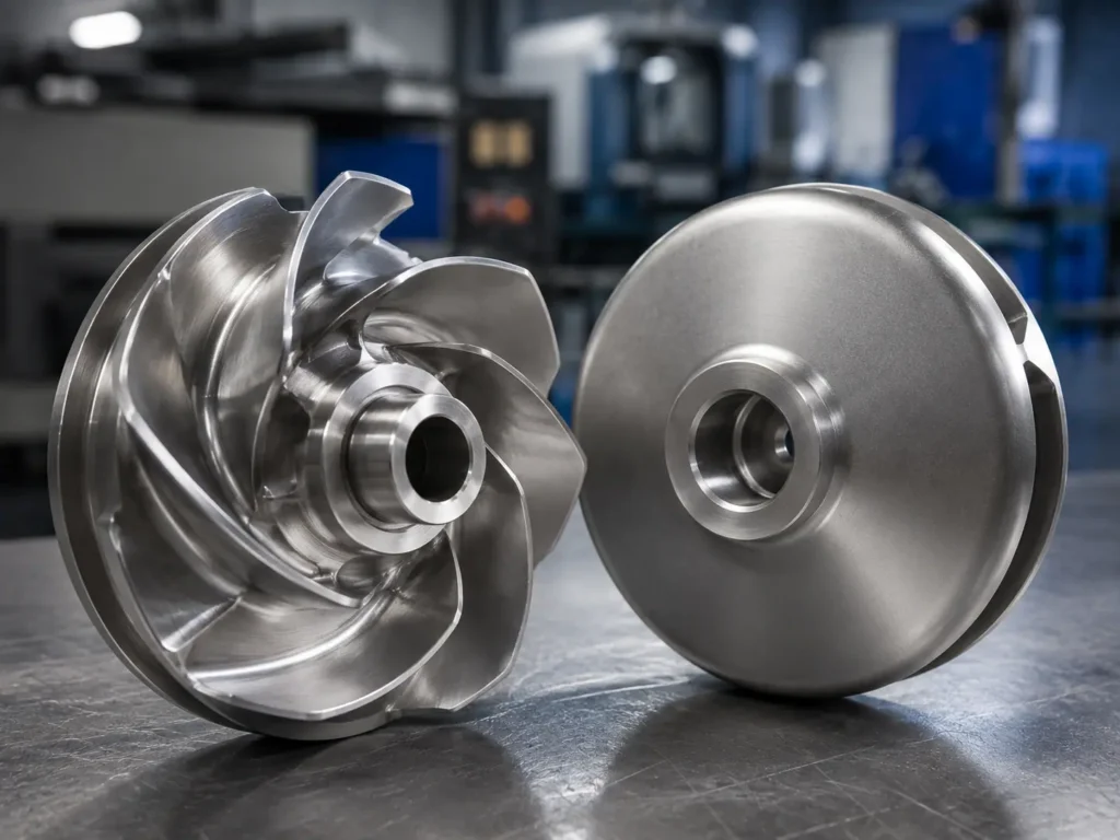
Impeller casting tolerance is the permitted dimensional variation of an impeller in its as-cast or rough-cast condition. It is not the same as the final machining tolerance on the bore, hub, mounting face, wear-ring diameter, keyway, runout surface, or other functional feature.
The buyer and manufacturer should separate casting-controlled geometry from finish-machined geometry on the drawing. Casting tolerance depends on the casting process, alloy, part size, wall thickness, pattern and core design, draft, shrinkage compensation, heat treatment, distortion, inspection access, and quantity. There is no responsible single tolerance value for every cast impeller.
Matson can review suitable cast impeller projects from controlled drawings, 3D models, physical samples, material specifications, quantities, machining requirements, and inspection plans. Final functional tolerances and equipment acceptance should remain controlled by the approved drawing and engineering owner.
[Image placeholder: Add a real inspection image showing an as-cast impeller blank and a finished machined impeller, with the casting envelope, core-controlled vane passages, machined bore, hub face, and wear-ring diameter clearly marked. Alt text: “Impeller casting tolerance and finished machining surfaces”]
Casting Tolerance Defines the Rough Part
A casting is a near-net shape. It reproduces vanes, shrouds, passages, hubs, and other geometry closely enough for the selected process, but it still contains casting variation, draft, surface texture, parting lines, gate and riser cleanup, and machining stock where required.
The casting drawing should define the rough condition needed to produce the finished part. The finished drawing should define the dimensions required for assembly and service. Mixing these two levels creates avoidable disputes.
For example, a rough hub diameter can be casting-controlled while the bore and mounting face are finish-machined. A vane passage may remain as-cast, while a wear-ring land receives machining allowance and a tighter final diameter. Each feature needs the correct requirement for its production stage.
Matson’s pump impeller casting guide explains how investment casting, sand casting, CNC finish machining, material selection, inspection, and balancing fit into one manufacturing route.
As-Cast, Rough-Machined, and Finished Tolerances
One impeller can have three valid dimensional states. The drawing and inspection report should identify which state applies.
| Production state | Main purpose | Typical control | Common mistake |
|---|---|---|---|
| As-cast | Produce the near-net blank with complete geometry and sufficient stock | Casting envelope, wall thickness, vane and shroud geometry, core location, draft, cleanup, and local machining allowance | Applying finished-machined tolerance to every rough surface |
| Rough-machined | Create datums, expose material condition, remove most stock, and prepare for later operations | Intermediate bore, face, diameter, stock remaining, datum relationship, and distortion review | Removing all stock before heat treatment or another distortion-producing stage |
| Finish-machined | Meet assembly, clearance, sealing, rotation, surface, and inspection requirements | Final size, form, orientation, location, surface finish, runout, and balance-related features | Accepting a finished feature only because the rough casting was within its envelope |
The inspection plan should never compare a rough casting result against a finished dimension without considering the specified machining stock.
Casting Process Changes Achievable Variation
Investment casting and sand casting use different tooling, mold materials, feeding systems, surface conditions, and dimensional controls. Even within one process name, capability changes with foundry method, pattern material, mold construction, alloy, part size, geometry, and production quantity.
Investment casting may suit smaller or detailed impellers and can provide useful near-net geometry. Sand casting can be practical for larger or heavier impellers and a wide range of industrial alloys. Neither process automatically guarantees a specific tolerance on every feature.
The supplier should review:
- Overall diameter and axial width
- Hub and shroud section thickness
- Vane length, thickness, spacing, and curvature
- Core-supported internal passages
- Parting-line location
- Gate and riser placement
- Areas that remain as-cast
- Areas requiring machining allowance
- Measurement and inspection access
A process selected only from part weight or material name may miss the actual geometry risk.
Shrinkage Compensation Is Not a Universal Scale Factor
Molten metal contracts during solidification and cooling, but a complex impeller does not shrink as a perfectly uniform model. Thick hubs, thin vanes, shrouds, abrupt section changes, cores, restraints, and local feeding conditions affect the final shape.
Pattern or tool design may include shrinkage compensation, but the correct compensation comes from the alloy, casting route, geometry, tooling experience, and approved process. A generic percentage copied from another part does not prove that the bore axis, vane passages, shroud spacing, or OD will land correctly.
First-article results should be used to confirm or adjust controlled tooling and process data. Any adjustment must protect the approved finished geometry rather than simply making the next rough casting resemble the previous one.
Core Shift Affects Internal Geometry
Closed and shrouded impellers may depend on cores or other mold features to create internal passages. If a core shifts, the external casting can appear acceptable while vane thickness, passage width, wall thickness, or symmetry changes inside the part.
Core-related controls may include:
- Core location references
- Passage-width checks
- Wall-thickness measurements
- Vane-to-shroud relationship
- Minimum machining stock around functional surfaces
- Sectioned development samples where justified
- Approved radiographic or other inspection in selected critical zones
The buyer should identify which internal features are functionally important. “Internal passage acceptable” is not a measurable requirement unless the drawing, model, inspection section, gauge, or agreed sample defines acceptance.
Distortion Needs a Datum and Stage
Impellers combine uneven sections and curved geometry. Distortion can arise during molding, pouring, solidification, shakeout, heat treatment, straightening, blasting, rough machining, or storage.
A flatness, axial width, shroud position, or runout-style check needs a datum and production stage. Measuring a rough shroud face from an unstable casting surface can give a result that is not repeatable. The supplier should establish how the part is supported and which surface or axis defines the inspection.
Distortion does not always mean the casting is unusable. If the blank retains sufficient stock and the finished geometry can be produced without violating minimum wall, repair rules, or material condition, machining may recover selected features. That decision must be based on the approved process and inspection evidence.
Machining Allowance and Casting Tolerance Work Together
Casting tolerance describes where the rough surface may occur. Machining allowance provides material that can be removed to reach the finished surface. Both must be reviewed around the same nominal geometry.
Too little local stock creates a cleanup risk when casting variation moves a surface toward the finished boundary. Excess stock increases casting weight, machining time, cutting load, material waste, distortion risk, and balance correction.
Allowance must also exist in the correct direction. A bore may have generous average stock while one side lacks cleanup because the rough feature is eccentric to the intended datum axis.
The impeller machining allowance article explains feature-specific stock, datum planning, rough and finish stages, defect exposure, worn samples, cost, and inspection records.
Do Not Use Casting Tolerance to Accept Defects
Dimensional tolerance and casting soundness are separate acceptance topics. A surface can be dimensionally within the casting envelope and still contain an unacceptable crack, cold shut, inclusion, shrinkage cavity, porosity, misrun, or damaged section.
Likewise, a clean-looking casting can be outside the required envelope or lack machining stock. Visual appearance does not replace dimensional inspection.
The buyer’s specification should identify:
- Critical zones
- Visual acceptance
- Dimensional acceptance
- Material verification
- Required nondestructive examination where applicable
- Repair permission and prohibited areas
- Reinspection after repair
- Minimum remaining wall and machining stock
Matson’s impeller casting defects checklist covers shrinkage, porosity, inclusions, cold shuts, misruns, cracks, dimensional distortion, inspection methods, repair control, and buyer documentation.
Worn Samples Cannot Define Casting Tolerance Alone
A physical sample is useful for understanding the real part, but service wear hides original geometry. Vane erosion, reduced OD, rubbed shrouds, corroded passages, repaired cracks, sleeved bores, and ground faces may all change measured dimensions.
Creating a casting model directly from a worn scan can embed damage into both the nominal geometry and tolerance plan. The buyer and manufacturer should separate:
- Reliable sample features
- Worn or repaired areas
- Finished surfaces
- Original as-cast surfaces
- Mating-equipment dimensions
- Reconstructed geometry requiring approval
Whenever possible, use the original drawing, unused reference part, assembly dimensions, prior report, or buyer-approved reconstruction decisions. Casting tolerance should apply to the approved rough-part definition, not to random variation in a failed sample.
Inspection Should Focus on Process Risk
Not every as-cast dimension requires the same inspection frequency. Critical and process-sensitive features deserve attention, while stable non-functional envelope dimensions may use a different sampling plan.
Useful rough-casting checks can include:
- Overall casting envelope
- Hub, shroud, and vane section thickness
- Core-controlled passage width
- Machining stock on the bore, faces, OD, and wear-ring lands
- Pattern mismatch and parting-line offset
- Gate and riser removal areas
- Distortion relative to an agreed datum
- Weight trend where it supports process control
Final inspection should then verify the finished dimensions, surface requirements, runout, and balance condition required by the drawing.
Matson’s impeller manufacturing capabilities include suitable casting, CNC machining, surface treatment, dimensional inspection, dynamic balancing, documentation, and export packing based on project requirements.
First Articles and Repeat Batches
A first casting can reveal whether the selected process, tooling, core system, allowance, and inspection plan can produce a usable blank. The approval record should identify both rough-casting results and final-machined results where applicable.
For repeat production, preserve:
- Drawing, casting model, and tooling revision
- Pattern, mold, core, and fixture identification
- Approved material and process route
- Critical rough dimensions and sampling plan
- Machining stock requirements
- Heat treatment and finishing sequence
- Inspection, deviation, and repair records
- Final dimensional and balance acceptance
Tool repair, pattern replacement, core change, process transfer, alloy change, or major parameter change may require revalidation. A finished drawing can remain unchanged while the rough-casting process changes enough to affect risk.
Impeller Casting Tolerance RFQ Checklist
Send the following before quotation:
- Controlled finished-part drawing and 3D model
- Rough-casting drawing or permission for supplier process development
- Material grade and governing specification
- Preferred casting route if already approved
- Surfaces that remain as-cast
- Surfaces requiring rough and finish machining
- Local machining allowance and minimum wall requirements
- Datum system for rough and finished inspection
- Vane, shroud, hub, passage, and core-controlled dimensions
- Casting surface, visual, and defect acceptance criteria
- Heat treatment, straightening, repair, and reinspection rules
- First-article and repeat-batch sampling requirements
- Required dimensional, material, NDT, and repair documents
- Final runout and dynamic-balancing requirements
- Quantity, annual volume, marking, and packing needs
This information lets the supplier review tooling, pattern and core strategy, shrinkage compensation, local stock, inspection access, machining sequence, defect risk, and repeatability before committing to the project.
Common Questions Buyers Ask
What is impeller casting tolerance?
It is the permitted dimensional variation of an impeller in its as-cast or rough-cast condition. It should be separated from the tighter final requirements applied after machining.
Is there one standard casting tolerance for every impeller?
No. Achievable variation depends on casting process, material, size, geometry, wall thickness, pattern and core design, heat treatment, distortion, inspection method, and foundry capability.
Why can a casting pass inspection but fail after machining?
The rough envelope may be acceptable while a functional area lacks local machining stock, contains a defect exposed by cutting, or is poorly located relative to the final datum.
Should vane passages use the same tolerance as the bore?
Usually they are controlled differently. Vane passages may remain as-cast or use profile and wall-thickness requirements, while the bore normally receives finish machining for shaft fit and datum control.
Can Matson inspect casting tolerance before CNC machining?
For suitable projects, Matson can review agreed rough-casting dimensions, machining stock, critical zones, inspection stages, and reports before finish machining. The exact scope should be confirmed during quotation.
Need an impeller casting tolerance plan reviewed for custom manufacturing? Send Matson the finished drawing, rough-casting requirements, model, material, casting route, machining surfaces, allowance, critical zones, quantity, and inspection documents through the custom impeller quote page.