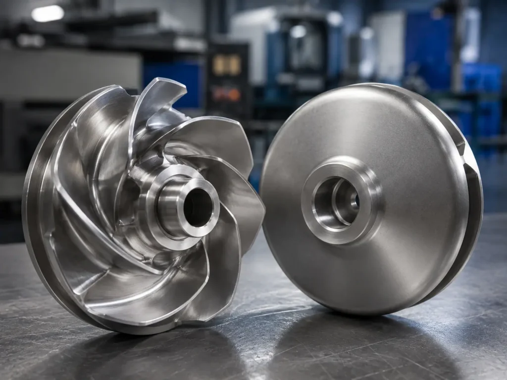
Impeller casting defects are discontinuities or dimensional problems created during pattern making, mold preparation, melting, pouring, solidification, shakeout, heat treatment, or finishing. Common examples include shrinkage cavities, gas porosity, inclusions, cold shuts, misruns, hot tears, cracks, dimensional distortion, surface laps, and local wall-thickness variation.
Not every visible mark is automatically a reject, and not every serious defect is visible on the surface. Acceptance depends on the approved drawing, material standard, service condition, defect location, size, depth, inspection method, repair rules, machining allowance, balancing requirement, and buyer specification.
For a custom impeller RFQ, buyers should define the critical zones, required inspection, acceptance criteria, permitted repairs, documentation, and traceability before production. Matson can review selected cast impeller projects from drawings, 3D files, samples, materials, quantities, and quality requirements.
[Image placeholder: Add a real foundry and inspection image showing a cast pump impeller with marked shrinkage, porosity, inclusion, cold-shut, crack, machining allowance, and critical bore or vane-root zones. Alt text: “Impeller casting defects and inspection zones on a cast pump impeller”]
Main Impeller Casting Defects
The defect name is useful only when it connects to location, cause, risk, and acceptance. A small surface indication in a non-critical cleanup area is different from a cavity at the hub, vane root, bore allowance, sealing surface, or highly stressed section.
| Casting defect | Typical appearance or location | Buyer review point |
|---|---|---|
| Shrinkage cavity or shrinkage porosity | Internal or exposed voids in areas that solidify late, including heavy hubs, thick transitions, or feeding-sensitive sections. | Location, depth, remaining wall, machining exposure, stress, leakage risk, and permitted repair. |
| Gas porosity | Rounded pores or clusters at the surface or inside the casting. | Source, distribution, sealing surfaces, pressure boundary relevance, machining exposure, and acceptance level. |
| Slag, oxide, sand, or other inclusion | Foreign material trapped in the metal, sometimes exposed after machining or blasting. | Type, size, depth, critical-zone location, bond, fatigue or erosion risk, and removal method. |
| Cold shut or cold lap | A line where metal streams met without complete fusion. | Whether it is superficial or crack-like, its direction, depth, location, and inspection evidence. |
| Misrun or incomplete fill | Missing thin edges, vane tips, corners, or sections that did not fill completely. | Geometry loss, hydraulic-profile impact, minimum thickness, and whether repair is permitted. |
| Hot tear or crack | Irregular separation in restrained or high-stress solidification zones. | Treat as a serious indication requiring defined inspection and engineering disposition. |
| Dimensional distortion | Warped shroud, shifted vane, off-center hub, incorrect eye, excessive runout, or uneven width. | Datum, profile tolerance, machining allowance, fit, clearance, runout, and balance impact. |
The same casting can contain more than one defect mechanism. Grinding a surface until an indication disappears does not prove that the underlying condition is acceptable.
Why Impeller Geometry Is Difficult to Cast
Impellers combine thin vanes, curved passages, thick hubs, shrouds, changes in section thickness, and surfaces that may be difficult to feed or inspect. Metal must fill the complete geometry while vents, gates, risers, mold materials, temperature, and solidification are controlled.
Risk increases when:
- Thin vane edges connect to heavy hubs or shrouds
- Wall thickness changes abruptly
- Internal passages restrict mold or core access
- The alloy has demanding fluidity or solidification behavior
- The casting route is changed without validation
- Machining allowance hides the final critical surface location
- The sample geometry is worn, repaired, or incomplete
- The drawing does not define minimum wall and critical zones
A casting supplier should review manufacturability before tooling. This does not mean changing the hydraulic geometry without approval. Proposed fillets, thickness changes, split lines, draft, feeding features, or machining allowances must be agreed with the equipment owner.
Matson’s pump impeller casting article explains the broader pattern, molding, pouring, heat-treatment, machining, and quality-control route.
Shrinkage at the Hub and Vane Root
The hub is often heavier than nearby vanes. Vane roots and shroud transitions also create changes in section thickness. These areas can solidify later and require careful feeding and process control.
Shrinkage near the hub matters because the hub carries the bore, keyway, mounting face, and torque path. A cavity exposed during bore machining may reduce the usable section or interrupt a functional surface. Shrinkage at a vane root can create fatigue, erosion, or crack-propagation concerns under the actual duty.
The buyer should define whether the hub, vane roots, bore allowance, mounting face, and balance-critical zones require additional inspection. Surface appearance alone may not reveal internal shrinkage.
Porosity Can Appear After Machining
A cast blank may look acceptable after blasting, then reveal pores when the bore, hub face, wear-ring diameter, eye, or shroud is machined. The machining drawing should therefore identify how much material will be removed and which finished surfaces are critical.
When porosity is exposed, record:
- Part and heat or batch identification
- Exact location and machined feature
- Indication size, depth, distribution, and photographs
- Remaining wall or section thickness
- Whether the surface controls fit, sealing, clearance, fatigue, or corrosion
- Inspection method and result
- Proposed disposition: accept, rework, repair, or reject
Do not fill a pore with weld, metal-loaded compound, or another repair material without buyer approval. The repair may affect material properties, corrosion, machining, heat treatment, runout, and balance.
Inclusions and Surface Indications Need Identification
Sand, slag, oxide, refractory, and other inclusions can appear as surface marks, embedded material, or internal discontinuities. Their risk depends on type, bond, size, depth, location, and service.
An inclusion at a non-functional surface is not equivalent to one at a vane leading edge, hub transition, wear-ring surface, sealing diameter, or machined bore. In abrasive or corrosive service, an inclusion or poorly bonded repair may become a local attack point.
Visual inspection should occur before and after blasting, grinding, heat treatment, and machining as appropriate. If an indication is removed, document the final geometry and minimum wall rather than reporting only that the surface was cleaned.
Cold Shut, Misrun, and Incomplete Vane Geometry
Thin vane tips and long flow paths can be difficult to fill. A misrun can leave a missing edge or incomplete section. A cold shut can create a seam-like indication where metal fronts met without fully joining.
These defects should not be disguised by grinding the neighboring surface. Compare the part against the approved 3D model, profile sections, vane thickness, leading and trailing edges, passage width, and minimum wall.
For a pump impeller, incomplete vane geometry can affect mass distribution and the approved hydraulic shape. Matson should manufacture the drawing-controlled part, while hydraulic-performance disposition remains with the pump OEM or engineering owner.
Cracks Require Clear Disposition
Crack-like indications, hot tears, and separations near vane roots, hubs, shrouds, sharp transitions, or heavy sections deserve conservative treatment. Visual inspection alone may not define their full extent.
The buyer’s specification should state the required inspection method, acceptance criteria, repair permission, qualification, heat treatment, reinspection, and documentation. If repair is not permitted in a critical zone, the casting should not enter production simply because delivery is urgent.
Avoid vague dispositions such as “ground smooth” or “welded and okay.” A traceable disposition identifies the indication, location, size, evaluation, repair procedure, personnel qualification where required, heat treatment, final inspection, and buyer approval.
Dimensional Defects Can Survive a Good Visual Inspection
An impeller can look clean and still have:
- Off-center bore allowance
- Shifted hub or eye
- Unequal vane spacing
- Incorrect vane profile or thickness
- Warped front or back shroud
- Wrong overall width
- Insufficient machining stock
- Excessive face or radial runout
- Incorrect rotation or mirrored geometry
These problems affect fit, casing clearance, machining, and balance. Dimensional inspection should use the correct datums and controlled drawing or model.
The pump impeller dimensions checklist covers OD, eye, bore, hub, vane profile, wear-ring surfaces, runout, and drawing data.
Match Inspection to the Defect Risk
No single inspection method finds every casting defect. The buyer and manufacturer should agree on the scope according to material, service, geometry, critical zones, and consequences of failure.
| Inspection approach | Useful for | Limitation to remember |
|---|---|---|
| Visual and dimensional inspection | Surface condition, incomplete fill, obvious cracks, geometry, dimensions, and runout. | Cannot confirm all internal discontinuities. |
| Liquid penetrant testing | Selected surface-breaking indications on suitable nonporous materials. | Does not show subsurface or internal defects and requires proper surface preparation. |
| Magnetic particle testing | Selected surface and near-surface indications in suitable ferromagnetic materials. | Not applicable to all alloys or all geometries. |
| Radiographic testing | Selected internal volumetric discontinuities and critical regions. | Geometry, access, orientation, interpretation, cost, and sensitivity affect results. |
| Ultrasonic testing | Selected internal discontinuities in sections suitable for ultrasonic examination. | Complex impeller geometry and thin vanes can limit access and interpretation. |
| Material verification | Grade, chemistry, heat or batch linkage, and traceability. | Material identity does not prove casting soundness or dimensions. |
Inspection acceptance should reference the buyer’s drawing, specification, or agreed standard. Adding “100% NDT” to an RFQ without method, zones, acceptance level, and report requirement is not precise enough.
Casting Repair Must Be Agreed Before Production
Some projects permit qualified weld repair in defined non-critical areas. Others prohibit repair completely or restrict it by location, size, material, or service.
The RFQ should state:
- Whether repair is allowed
- Prohibited critical zones
- Maximum indication and excavation size
- Approved repair procedure and filler material
- Personnel qualification requirements
- Preheat, interpass, post-weld heat treatment, and cooling controls
- Final machining and dimensional restoration
- Repeat NDT and acceptance
- Repair map, photographs, and buyer approval
Repair can change mass distribution. A repaired impeller may need final runout and dynamic-balancing checks after all machining and surface treatment.
What Buyers Should Put in the RFQ
For a cast impeller project, provide:
- Controlled 2D drawing and 3D model
- Exact material grade and governing specification
- Casting method if already approved
- Critical zones and minimum wall thickness
- Machining allowance and finished surfaces
- Dimensional and profile tolerances
- Visual, dimensional, NDT, and material-inspection requirements
- Defect acceptance criteria and repair rules
- Heat treatment, surface treatment, and certificate requirements
- Operating speed and dynamic-balancing requirement
- First-article, batch, traceability, and report requirements
- Quantity, repeat-order forecast, marking, and packing
Matson’s impeller manufacturing capabilities include casting, CNC machining, surface treatment, dimensional inspection, dynamic balancing, material documentation, and export packing for suitable projects.
Common Questions Buyers Ask
What are the most common impeller casting defects?
Common defects include shrinkage cavities, gas porosity, inclusions, cold shuts, misruns, hot tears, cracks, dimensional distortion, surface laps, and wall-thickness variation.
Is every casting pore a reason to reject an impeller?
Not automatically. Acceptance depends on size, depth, location, finished wall, material, service, machining exposure, inspection results, and the buyer’s agreed criteria. Critical-zone defects require conservative review.
Can casting defects be welded?
Only when the project specification permits repair and the location, size, procedure, filler, personnel, heat treatment, reinspection, dimensions, and buyer approval are controlled.
Which inspection finds internal casting defects?
Radiography or ultrasonic examination may detect selected internal discontinuities, but suitability depends on geometry, material, section thickness, access, orientation, and the required sensitivity. No method finds every defect.
Can Matson provide cast impeller inspection documents?
For selected projects, Matson can prepare agreed material, dimensional, visual, NDT, balancing, and inspection records. The exact scope and acceptance criteria should be confirmed before quotation.
Need a cast impeller reviewed for custom manufacturing? Send Matson the drawing, model, material, critical zones, machining allowance, inspection and repair requirements, operating speed, balance criteria, quantity, and document list through the custom impeller quote page.