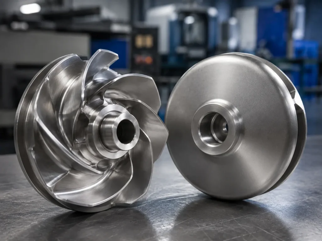
Impeller runout tolerance is the maximum permitted indicator variation when a specified impeller surface is rotated around a defined datum axis. It is not one universal value: the drawing or approved inspection plan should state the datum, measured feature, measurement condition, tolerance, and acceptance stage.
Radial runout is commonly checked on outside diameters, wear-ring diameters, or other cylindrical features. Face or axial runout is checked on mounting faces, shrouds, or other surfaces perpendicular to the axis. Buyers should not treat runout, concentricity, dimensional size, and dynamic balance as interchangeable requirements.
For a custom impeller RFQ, define how the part is mounted, which datum establishes the rotation axis, where the indicator contacts the part, whether the check occurs before or after coating and balancing, and what report is required. Matson can review these requirements against the supplied drawing, model, sample, material, quantity, and manufacturing route.
[Image placeholder: Add a real inspection image showing an impeller mounted on a controlled arbor between centers or on a fixture, with one dial indicator checking a radial diameter and another checking a face. Alt text: “Impeller radial and face runout inspection using dial indicators”]
What Impeller Runout Actually Measures
Runout records the variation seen by an indicator while a part rotates around a specified axis. The result combines the geometry of the measured surface with its relationship to the selected datum and the actual mounting condition.
That makes the setup part of the requirement. The same impeller can produce different readings when it is located from a finished bore, an unfinished casting surface, a worn sample bore, a temporary arbor, a taper, a keyway, or an assembled shaft. A drawing that says only “runout 0.05 mm,” without identifying the datum and feature, is incomplete for reliable inspection.
The detailed pump impeller dimensions checklist explains how bore, hub, eye, OD, shrouds, wear-ring surfaces, and vane geometry should be controlled together.
Radial, Face, and Axial Runout
Different runout terms are sometimes used loosely in RFQs. Buyers and manufacturers should confirm the exact feature and measurement direction rather than relying on the term alone.
| Runout check | Typical impeller feature | What the buyer should define |
|---|---|---|
| Radial runout | Outside diameter, wear-ring diameter, hub diameter, or another cylindrical surface | Datum axis, exact indicator track, full or partial circumference, surface condition, and maximum indicator reading |
| Face runout | Hub mounting face, shroud face, back face, or seal-related face | Datum axis, indicator radius, excluded interruptions, and whether the surface is finished or as-cast |
| Axial runout | Often used to describe face variation in the axial direction | Whether the requirement means face runout, axial position, flatness, or total axial movement |
| Assembly runout | Impeller mounted on the production shaft, taper, sleeve, or complete rotating assembly | Assembly components, tightening method, key or taper condition, torque, orientation, and repeatability |
A runout check should also state whether a full indicator reading, peak-to-peak value, or another reporting convention is required. Supplier and buyer must use the same definition.
Runout Is Not the Same as Concentricity
Concentricity, coaxiality, circular runout, total runout, circularity, cylindricity, and position describe different geometric controls. A general note such as “all diameters concentric” does not tell an inspector which datum, feature, tolerance zone, or verification method applies.
Runout can be a practical functional control because it evaluates a surface while the part rotates around the datum axis. However, it may include effects from surface waviness, lobing, taper, local casting texture, burrs, dirt, or mounting error. It should not be used as a substitute for every individual size and form tolerance.
For new or revised drawings, the equipment owner should select controls based on fit, clearance, sealing, rotation, and service risk. Matson can review manufacturability and inspection access but should not invent the functional acceptance requirement for the pump or machine.
Runout Is Not Dynamic Balance
An impeller may meet a runout tolerance and still be unbalanced because mass is distributed unevenly. It may also pass a dynamic balance requirement while a functional diameter or face exceeds its runout limit.
Runout is a geometric and mounting relationship. Dynamic balancing evaluates mass distribution under a defined balancing condition. The balance requirement needs operating speed, balance standard or acceptance grade, balancing planes, arbor or assembly condition, key convention, correction limits, and report expectations.
The custom impeller dynamic balancing guide explains why bore condition, assembly state, correction method, and acceptance evidence must be agreed separately from runout.
Establish the Datum Before Measuring
The datum should reproduce the feature that controls the impeller’s installed rotation as closely as practical. Depending on the design, that may be:
- A finished straight bore on a controlled arbor
- A taper seated on a matching master or production shaft
- Two center features
- A pilot diameter and mounting face
- A shaft, sleeve, or hub assembly supplied by the buyer
- Another drawing-defined datum system
The bore or taper must be clean and free from raised edges. The arbor, centers, shaft, bearings, and fixture must be suitable for the required tolerance. If fixture error is a meaningful share of the permitted runout, the result cannot reliably distinguish the part from the measurement system.
For sample-based work, a worn, fretted, corroded, repaired, or distorted bore may not provide a trustworthy axis. The buyer may need to supply the mating shaft, original drawing, assembly reference, or a decision about how the intended axis will be reconstructed.
A Practical Measurement Sequence
A repeatable inspection method can follow this sequence:
- Confirm the drawing revision, datum system, feature, tolerance, and inspection stage.
- Clean the datum and measured surface, and remove only permitted burrs or contamination.
- Verify the arbor or fixture condition and record its identification when required.
- Mount the impeller using the agreed seating, tightening, key, spacer, and orientation method.
- Position the indicator at the drawing-defined track and direction.
- Rotate the part slowly through the required angle without applying force that changes its seating.
- Record the maximum and minimum readings and calculate the agreed reported result.
- Repeat the mounting if repeatability must be demonstrated.
- Record the feature, datum, setup, stage, instrument, result, and disposition.
For interrupted vane edges, rough cast surfaces, welds, keyways, holes, or coating texture, the drawing or inspection plan should define where readings are taken and which interruptions are excluded. Otherwise, two inspectors can follow reasonable methods and still report different results.
Where Runout Should Be Checked
Not every visible surface needs a tight runout control. The highest-value checks usually correspond to functional interfaces and rotating clearances.
Typical locations include:
- Finished bore or taper relative to the intended rotation axis
- Wear-ring or seal-related diameters
- Hub pilot and mounting face
- Front or rear shroud surfaces near a controlled clearance
- Outside diameter when it affects casing clearance
- Coupling or shaft interface on an assembled rotor
Vane tips and as-cast hydraulic surfaces may require profile, position, or dedicated dimensional inspection rather than an indicator running directly over irregular casting texture. The inspection method should match the feature.
Manufacturing Steps That Can Change Runout
Runout can change at multiple stages. A casting may contain distortion or uneven machining stock. A part may shift during rough machining, stress relief, heat treatment, welding, finish machining, coating, or final assembly. An inaccurately located bore can make every external feature appear eccentric when the impeller is mounted from that bore.
The machining plan should protect the functional datum and preserve enough stock for finishing critical diameters and faces. For tight relationships among a bore, face, pilot, and wear-ring diameter, machining them in a controlled setup or through a documented datum-transfer process may reduce accumulated error.
Matson’s CNC machined impeller guide covers datum planning, casting allowance, multi-axis access, inspection, and drawing-controlled finish machining.
Check Runout at the Correct Production Stage
A buyer should specify whether runout is checked:
- After rough machining
- After heat treatment or stress relief
- After finish machining
- After weld repair
- After coating or surface treatment
- Before and after balancing correction
- On the bare impeller or final rotating assembly
A coating can alter a measured diameter or create local thickness variation. Weld repair can introduce distortion. Balance correction by grinding or material removal can affect a nearby functional surface if correction zones are not controlled. Final acceptance should occur after all operations capable of changing the relevant geometry, unless the process plan explicitly requires intermediate checks as well.
Do Not Copy a Tolerance Without Functional Context
There is no responsible single answer to “What is the standard impeller runout tolerance?” The usable value depends on diameter, speed, shaft and bore fit, bearing arrangement, casing clearance, wear-ring clearance, sealing function, material, manufacturing state, measurement capability, and the governing equipment drawing or standard.
A tolerance copied from another impeller may be unnecessarily expensive or functionally unsafe. Tightening a number without controlling the datum, surface finish, roundness, fixture, and temperature can also create an inspection requirement that is not repeatable.
If an old drawing is missing the requirement, the pump OEM, equipment owner, or qualified engineer should determine the functional limit. A manufacturer can then confirm feasibility, inspection method, cost, and production controls.
What an Inspection Report Should Show
For a critical impeller, a report should contain enough information to connect the numeric result to the actual setup. Useful fields include:
- Part number, revision, serial or batch identification
- Material and production stage
- Datum and mounting method
- Measured feature and indicator location
- Required tolerance and measured result
- Instrument identification and calibration status when specified
- Arbor, shaft, or fixture identification when relevant
- Environmental or temperature condition when relevant
- Inspector, date, acceptance status, and approved deviation reference
A report that says only “runout OK” is difficult to audit. Photos or a marked drawing can help when several similar diameters or faces are present.
Matson’s impeller manufacturing capabilities cover suitable casting, CNC machining, surface treatment, dynamic balancing, dimensional inspection, documentation, and export packing projects.
Impeller Runout RFQ Checklist
Include the following information before quotation:
- Controlled 2D drawing and 3D model, if available
- Impeller type, material grade, and manufacturing route
- Datum features and installed rotation axis
- Radial, face, or assembly runout feature and tolerance
- Indicator track or measurement location
- Bore, taper, keyway, pilot, face, and shaft-fit details
- Mating shaft, sleeve, nut, spacer, or master required for inspection
- Surface condition and excluded interruptions
- Inspection stage before or after coating, repair, and balancing
- Mounting torque, key convention, and assembly orientation if relevant
- Measurement repeatability, sampling, and report requirements
- Operating speed and separate dynamic-balance requirement
- First-article approval and deviation process
- Quantity, repeat-order forecast, marking, and packing needs
This information lets the supplier evaluate tooling, datum control, machining sequence, inspection access, gauge capability, and documentation before committing to the requirement.
Common Questions About Impeller Runout
What is impeller radial runout?
It is indicator variation measured in a radial direction on a specified cylindrical feature while the impeller rotates around a defined datum axis. The drawing should identify both the feature and datum.
What is impeller face runout?
It is indicator variation measured on a face while the impeller rotates around the specified axis. The indicator radius, datum, surface condition, and excluded interruptions should be defined.
What is a normal impeller runout tolerance?
There is no universal value suitable for every impeller. The equipment drawing or approved inspection plan should set it from functional fit, clearance, speed, diameter, material, manufacturing condition, and measurement capability.
Can an impeller pass balance but fail runout?
Yes. Dynamic balance controls mass distribution under a defined balancing condition, while runout controls a geometric relationship to a datum axis. Both may need separate acceptance criteria.
Should runout be measured before or after coating?
The buyer should define the stage. If coating thickness can affect the functional diameter or face, final runout may need verification after coating. Critical parts may also require an earlier machined-condition record.
Need a custom impeller runout requirement reviewed for manufacturing? Send Matson the controlled drawing, datum scheme, measured features, tolerance, mating parts, operating speed, balance requirement, quantity, and report needs through the custom impeller quote page.