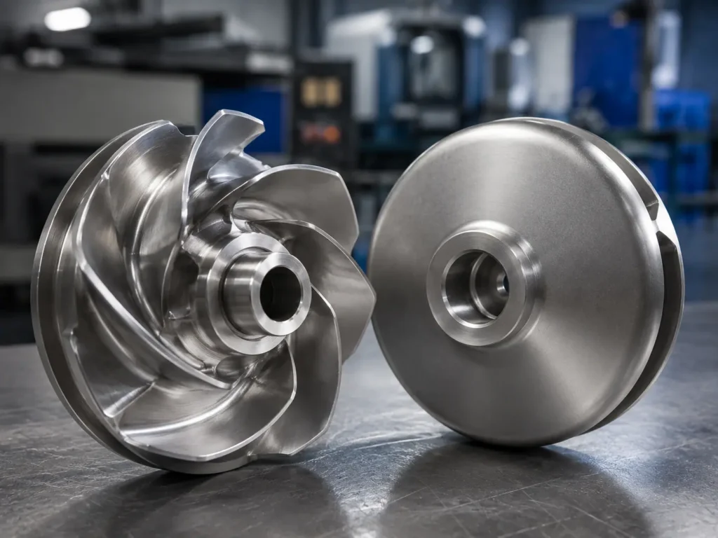
Impeller vanes are the curved or straight passages that guide liquid through a pump impeller. Their count, inlet angle, outlet angle, thickness, profile, spacing, and relationship to the eye and shrouds affect hydraulic performance, casting difficulty, inspection access, wear behavior, and balance.
Short answer: buyers sourcing custom pump impellers should not describe the vanes only as “curved” or “straight.” A useful RFQ should include the approved drawing or 3D model, vane count, rotation direction and viewing side, inlet and outlet geometry, shroud structure, impeller diameter, bore, hub, material, pump speed, liquid condition, and balancing requirement.
Matson manufactures centrifugal pump impellers from drawings, 3D files, samples, and project specifications. Final vane design and pump performance approval should remain with the pump OEM or engineering owner. Matson’s role is to review manufacturability, casting or fabrication route, CNC finishing, inspection, and balance requirements against the supplied specification.
What Are Impeller Vanes?
Impeller vanes are the working surfaces between the inlet eye and the outer discharge area of a pump impeller. As the impeller rotates, the vane passages guide the liquid and transfer energy from the rotating component into the flow.
The terms “vane” and “blade” are often used loosely. In pump discussions, “vane” is common. Fan and mixer equipment may use “blade” more often. The important point for manufacturing is not the label. It is the exact geometry shown on the approved drawing or model.
A vane cannot be reviewed in isolation. It connects to the eye, hub, front shroud, back shroud, outlet width, outside diameter, and casing clearance. A change to one area can affect the rest of the rotating part.
Vane Types Buyers Commonly See
You will hear vanes described as single vane, multi vane, straight vane, open vane, or closed vane. Each phrase points at a different part of the geometry — they are not interchangeable specifications, and getting the wrong one onto an RFQ leads to the wrong part.
| Vane description | What it usually describes | Practical manufacturing concern |
|---|---|---|
| Single vane impeller | One main flow passage, often discussed where larger solids passage is important. | Asymmetric mass, complex passage geometry, worn-sample distortion, and balancing need careful review. |
| Multi vane impeller | Several repeated vane passages around the impeller. | Consistent spacing, vane thickness, passage width, casting fill, and repeatability between vanes matter. |
| Straight vane impeller | Vanes with a relatively straight radial form rather than a strongly curved profile. | Rotation direction, leading and trailing edges, vane thickness, hub connection, and service condition still need confirmation. |
| Curved vane impeller | Vanes with a controlled curved profile between inlet and outlet. | The curve should come from the drawing or 3D model. A side photo rarely captures the true profile. |
| Open vane impeller | Vanes exposed on one or both sides rather than fully enclosed between two shrouds. | Vane edge wear, open-side clearance, casing or wear-plate relationship, and distortion are important. |
| Closed vane impeller | Vanes enclosed between front and back shrouds in a closed impeller structure. | Internal passage inspection, casting access, shroud thickness, wear-ring fit, and hidden defects need attention. |
Vane type should come from the original pump design. A single-vane arrangement should not be changed to a multi-vane arrangement because another style appears easier to cast. Likewise, open and closed structures should not be exchanged without approval from the pump engineering owner.
Vane Angle and Profile Are Not One Dimension
An impeller vane angle can refer to the inlet angle, outlet angle, local blade angle, or a measurement taken at a particular radius. A number without a defined location and reference direction is easy to misunderstand.
The vane profile is also three-dimensional on many centrifugal impellers. It may twist from the eye toward the outlet. Its height may change along the passage. The leading edge may be rounded or shaped differently from the trailing edge. Shrouded impellers can hide much of this geometry from normal photographs.
This creates a common RFQ problem. A buyer sends the outside diameter, bore, vane count, and one front photo. The information looks useful, but it is not enough to reproduce the vane passages. A correct-looking impeller can still have the wrong inlet angle, outlet width, passage area, rotation direction, or shroud relationship.
For broader context, Matson’s pump impeller design factors guide explains how diameter, eye geometry, vane arrangement, fit, material, and operating condition should be reviewed together.
Does the Number of Vanes Matter?
Yes, but vane count should be treated as an approved design input, not a factory preference.
The number of vanes influences passage size, blockage, flow guidance, casting complexity, mass distribution, and inspection access. Fewer vanes may leave larger passages, while more vanes create narrower repeated passages. That simplified statement does not tell a buyer which count is correct for a pump.
For replacement or OEM manufacturing, confirm:
- Exact vane count
- Whether splitter or partial vanes are present
- Vane spacing and clocking around the impeller
- Inlet and outlet widths
- Leading-edge and trailing-edge positions
- Rotation direction and the side from which it is viewed
- Whether the old sample has missing, repaired, or heavily worn vanes
Never count only the visible outlets on a damaged shrouded impeller and assume every internal passage is intact. Debris, corrosion products, old weld repairs, and broken edges can hide the original structure.
Wear Patterns on Pump Impeller Vanes
Vanes do not wear in one universal pattern. Damage location and surface texture can provide useful clues, but they do not prove the cause by themselves.
| Observed vane condition | Possible context | What to confirm before manufacturing |
|---|---|---|
| Pitting near the inlet edge | Cavitation or unstable suction-side conditions. | Operating point, suction condition, liquid temperature, pump speed, and damage photos. |
| Directional thinning through the passage | Abrasion from sand, grit, slurry, or suspended solids. | Solids content, particle size, current material, wear interval, and minimum remaining thickness. |
| Uneven corrosion across several vanes | Material mismatch, chloride exposure, chemical attack, or stagnant areas. | Liquid chemistry, pH, chloride, temperature, cleaning process, and material grade. |
| Crack at a vane-to-shroud connection | Stress concentration, vibration, casting defect, overload, or previous repair. | Crack location, operating speed, balance history, casting quality, and repair record. |
| One vane differs from the others | Impact damage, repair welding, grinding, or severe localized wear. | Compare every passage, mark repaired areas, and use the approved model where possible. |
| Polished or rubbed vane edge | Contact, foreign material, deformation, or incorrect clearance. | Casing condition, assembly position, shaft runout, bore fit, and clearance data. |
The wrong lesson is to copy the most damaged vane exactly. When a sample has one broken or repaired vane, compare it with the remaining vanes and check the original drawing. Matson’s pump impeller failure guide provides a wider review of cavitation, abrasion, corrosion, fit, clearance, casting, and balance problems.
Casting and CNC Machining Checks
Complex vane passages are often formed during casting. The route may use investment casting or sand casting based on size, material, geometry, quantity, allowance, and project requirements. Critical fit surfaces can then be CNC machined.
Vane manufacturing review should cover:
- Minimum and maximum vane thickness from the approved model
- Smooth transitions at vane-to-hub and vane-to-shroud connections
- Casting draft, core access, and internal passage cleanout
- Machining allowance near the eye, outlet, bore, hub, and wear surfaces
- Accessibility for grinding, polishing, or internal inspection
- Leading-edge and trailing-edge condition
- Vane spacing and passage consistency
- Casting defects, weld repairs, and buyer acceptance rules
- Dimensional inspection method for internal geometry
- Final runout and dynamic balancing requirement
Internal vane surfaces are harder to measure than the bore or outside diameter. A 3D model can be more valuable than a simple 2D outline when the passage twists or changes height. If only a sample is available, section templates, inspection gauges, scanning data, and comparison between repeated passages may be needed according to project requirements.
The broader impeller manufacturing process should connect casting, CNC machining, surface treatment, dimensional inspection, material documentation, and balancing. Treating vane geometry as a separate decorative feature misses the real production risk.
Why Final Balancing Comes After Vane Work
Uneven vane thickness, trapped casting material, local grinding, repair welding, corrosion allowance, or inconsistent passages can shift the mass distribution of an impeller. This is especially important after final machining and surface correction.
Balancing should not be used to hide incorrect geometry. First confirm the vane count, passage form, bore concentricity, hub and shroud condition, runout, and material removal. Then apply the balancing requirement stated by the drawing or buyer.
For an RFQ, provide the operating speed, impeller diameter and mass if available, required balance grade, whether the impeller is balanced alone or as an assembly, and the required report format. There is no single balance instruction that fits every pump impeller.
What to Send for an Impeller Vane RFQ
A useful quote package should let the manufacturing team understand both the rotating part and its service condition.
- Approved 2D drawing and 3D model where available
- Physical sample or clear inlet, outlet, side, hub, bore, and passage photos
- Vane count, including any splitter or partial vanes
- Inlet angle, outlet angle, vane profile, and reference locations
- Outside diameter, eye diameter, outlet width, vane height, and shroud details
- Bore, keyway, taper, thread, mounting face, and hub height
- Rotation direction with a clearly stated viewing side
- Material grade and required material certificate
- Liquid chemistry, temperature, solids, corrosion, and abrasion conditions
- Pump speed, balancing grade, inspection report, and acceptance criteria
- Sample quantity, batch quantity, and expected recurring demand
If a worn sample is the only reference, mark every repaired, broken, thinned, or ground vane. Also explain whether the sample failed suddenly or wore gradually. That information helps separate original geometry from service damage.
Common Questions We Actually Get
What are impeller vanes?
Impeller vanes are the working surfaces and passages that guide liquid through a pump impeller. Their geometry connects the inlet eye to the outer discharge area.
Is the number of vanes in an impeller important?
Yes. Vane count affects passage geometry, casting, mass distribution, and pump behavior. For custom manufacturing, use the approved drawing or model rather than selecting a count by general rule.
Can an impeller be manufactured from vane photos?
Photos help identify structure and damage, but they rarely define the full vane angle, profile, passage width, shroud relationship, and internal geometry. A drawing, 3D model, or reliably measured sample is safer.
Can Matson change the impeller vane design?
Matson can review vane geometry for manufacturability against a supplied drawing, model, sample, and project specification. Final hydraulic redesign and pump performance approval should remain with the pump OEM or engineering owner.
What causes uneven wear on impeller vanes?
Possible causes include cavitation, abrasive solids, corrosion, casing contact, foreign material, vibration, casting defects, or previous repair. Damage photos and operating information are needed before choosing a manufacturing response.
Send Us Your Drawing
Need a custom pump impeller reviewed from a drawing, 3D file, or worn sample? Send Matson the vane count, vane profile, rotation direction, impeller dimensions, bore and hub details, material, liquid condition, pump speed, balancing requirement, quantity, and inspection needs through the contact page. We can review the part from a casting, machining, inspection, and production perspective before quoting.