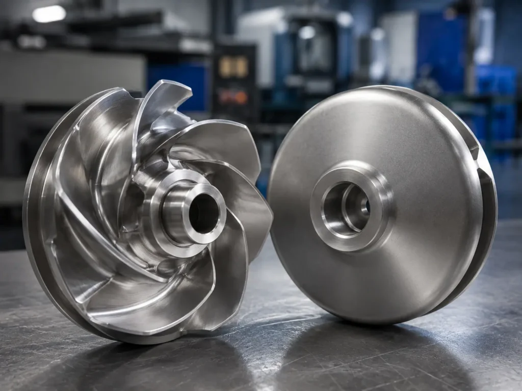
A worn pump impeller can lower the head and efficiency a pump develops at a given speed, but the size and shape of the change depend on where material has been lost, the pump design, clearances, and the liquid. The field operating point may also move because it is where the pump curve meets the system curve. Compare measured duty with the correct baseline curve before blaming the impeller alone.
What a pump curve tells you
A pump performance curve is not a single promised flow or pressure. The head-capacity (H-Q) curve shows the total head a particular pump configuration can develop across a range of flow rates at a stated speed and impeller diameter. A full performance sheet may also show efficiency, input power, and net positive suction head required (NPSHR). The Hydraulic Institute’s pump-curve reference describes these as characteristics of a specific pump model and operating speed; the certified curve should correspond to the pump and impeller trim actually supplied.
For diagnosis, keep two ideas separate:
- Pump curve: the pump’s hydraulic capability at the stated speed, impeller geometry, and test conditions.
- System curve: the head the piping and process require at each flow rate.
The intersection is the operating point. If the pump’s curve changes, the intersection can move. If the system curve changes because a strainer is blocked, a valve moved, a control strategy changed, or liquid levels differ, the operating point can also move even if the impeller has not changed. A low-flow complaint is not proof of an impeller fault.
Worn pump impeller effect on pump curve
Material loss can alter the impeller’s vane profile, inlet and outlet edges, shroud surfaces, and clearances. That changes how the rotating impeller transfers energy to the liquid and how much liquid recirculates internally. In many worn-pump cases, the result is lower developed head and hydraulic efficiency, especially when wear is substantial. However, there is no universal “worn impeller curve”: the effect depends on the damage location, pump type, running speed, wear-ring arrangement, and service condition.
Wear at the impeller itself and wear in the running clearances should not be treated as identical. Eroded or rounded vanes change the hydraulic geometry. Enlarged impeller-to-casing or wear-ring clearance can increase internal leakage from a higher-pressure region back toward a lower-pressure region, reducing useful delivery and efficiency. The Hydraulic Institute’s pump FAQs note that badly worn wear components can cause significant loss of head and flow, particularly in smaller pumps. KSB’s internal-leakage explanation describes how clearance flow contributes to losses.
| Observed condition | Potential hydraulic effect | What the curve or field data may show | Important limitation |
|---|---|---|---|
| Rounded, thinned, or eroded vane edges | Less effective energy transfer or altered flow guidance | Lower head at a comparable flow and speed; efficiency may also decline | The magnitude cannot be inferred from appearance alone. Confirm geometry and test or compare to a verified curve. |
| Increased wear-ring or running clearance | More internal leakage and reduced volumetric/hydraulic efficiency | Reduced delivered flow or head at the system operating point; performance loss can become more visible at lower flow for some designs | Measure the relevant clearance against the OEM drawing or specification; do not apply a generic limit. |
| Cavitation pitting or local surface damage | Surface roughness and profile change; continued damage can remove material | May coincide with unstable performance, vibration, or noise, but those symptoms have other causes too | Investigate suction conditions, NPSH margin, operating region, and liquid before assigning cause. |
| Deposits, scale, or solids buildup | Passage area and surface condition change | Flow/head and power may shift in a design-specific way | Deposits are not material-loss wear; inspection and cleaning may reveal the actual surface. |
| Corrosion, abrasion, or erosion-corrosion | Local thickness loss, roughness, and changed vane form | A changed H-Q response or efficiency is possible | Identify liquid chemistry, solids, particle size, velocity, and material before choosing a replacement grade. |
| Bent vane, cracked hub, loose fit, or rubbing | Hydraulic disturbance and/or mechanical risk | Vibration, noise, unstable operation, or performance change may occur | Stop and follow the site’s safety and equipment procedures; a curve comparison alone cannot clear a mechanical defect. |
The curve symptom is therefore evidence to investigate, not a damage photograph translated into a performance number. A small edge defect can matter in one design and have little measurable effect in another; a substantial clearance increase can be more consequential than a visually obvious but hydraulically remote mark.
Why flow can go down, stay similar, or appear to increase
When a pump curve drops at a given speed, the operating point usually moves along the system curve to a new intersection. In a system dominated by friction losses, that often means less flow and less head. But “worn impeller = lower flow” is too simple as a universal rule. Static head, control valves, parallel equipment, bypasses, tank levels, variable-speed control, and process changes all influence where the intersection lies.
An operator may observe a similar flow but lower discharge pressure because a control valve or speed controller is holding flow. Conversely, a system change can raise measured flow while head falls, even as the pump itself has lost capability. A pressure gauge at one nozzle is not the whole pump head: suction pressure, elevation, velocity effects, density, and measurement locations matter. If the duty has changed, compare like with like before interpreting a curve shift.
Power is also not a simple wear indicator. Input power depends on flow, head, liquid properties, and pump efficiency; motor current can be influenced by motor condition, voltage, power factor, speed, and measurement method. A reduction in flow does not automatically mean lower total energy use or prove a worn impeller. Review the pump curve and electrical readings together with the operating condition.
Symptoms that justify a curve comparison
Start a structured review when a pump no longer meets a documented duty, requires more speed or valve adjustment to achieve the same process result, or shows a sustained change in flow, differential pressure, vibration, or power relative to its own baseline. Compare conditions at the same speed and a known impeller diameter where possible. If a VFD has changed speed, first compare data at the actual measured RPM or use the manufacturer’s approved correction method; do not overlay curves at different speeds as if they were the same test.
| What changed in operation? | First checks beyond the impeller | Evidence that helps separate causes |
|---|---|---|
| Flow is below the original duty | Suction blockage, clogged strainer, closed/changed valves, air ingress, control setting, pump speed | Calibrated flow measurement, suction/discharge pressures, valve position, speed, liquid level |
| Head or differential pressure is low | Gauge/transmitter accuracy, suction condition, rotation, speed, system recirculation or bypass | Pressure readings at stated locations, elevations, flow, speed, approved pump curve |
| Vibration or noise increased | Cavitation, bearing/seal issues, misalignment, foundation, rubbing, imbalance, solids impact | Vibration trend and location, operating point, maintenance record, inspection findings |
| Power/current changed | Speed, flow, liquid density/viscosity, motor/electrical condition, recirculation, impeller trim | Input power when available, motor data, speed, flow/head, liquid properties |
| Performance declines gradually over months | Abrasive solids, corrosion, erosion, wear-ring clearance growth, deposits, process changes | Previous test reports, chemistry/solids trend, inspection photos, measured clearances |
For common damage mechanisms such as cavitation, abrasive wear, corrosion, and rubbing, use the broader pump impeller failure guide as a symptom and cause map. For material-loss patterns and service data used in RFQ review, see the impeller erosion article. Neither replaces an equipment-specific performance test or the pump OEM’s diagnosis.
A reliable before-and-after comparison
The fairest comparison uses a baseline curve and field readings captured under documented conditions. Use the curve for the exact pump model, impeller diameter/trim, and speed—not a family selection chart if a pump-specific test curve is available. Record flow, suction and discharge pressure, liquid temperature and properties, speed, valve positions, tank levels, and any parallel pumps or bypass flow. Note instrument ranges and calibration status as well.
Head should be compared on a consistent basis. Differential pressure alone may be a useful operational signal, but total pump head also accounts for suction and discharge measurement elevations and velocity terms where material. When liquid density differs from water, pressure and head are not interchangeable without the appropriate conversion. If the liquid is viscous or contains solids, published clean-water curves may not predict field performance directly; use the pump supplier’s approved corrections and operating data.
Normalize speed only with an appropriate method and within its limitations. The Hydraulic Institute’s pump-curve guidance describes affinity relationships for speed and limited impeller-diameter changes, but cautions that the assumptions and applicable limits matter. Wear is not the same as a controlled impeller trim: it can change roughness, clearances, vane shape, and efficiency in uneven ways. Do not estimate an exact worn curve by applying the diameter-trim relationship to a worn or damaged wheel.
Practical comparison workflow
- Find the reference. Retrieve the original pump curve, test certificate if available, pump model, impeller diameter, speed, and curve conditions (liquid and test standard).
- Confirm the current pump configuration. Check actual impeller diameter, rotation, speed, control settings, wear-ring parts, and whether a prior repair or trim changed the assembly.
- Stabilize and document the duty. Measure flow and suction/discharge conditions under steady operation; record valve positions, tank levels, liquid temperature, density or viscosity information, and parallel/bypass operation.
- Check the system before condemning the pump. Review strainers, filters, piping changes, valve positions, air leaks, bypasses, control logic, and process demand. The system curve may have changed.
- Plot like-for-like points. Compare measured head and flow with the correct pump curve at the documented speed and configuration. Add older field readings if they were collected reliably.
- Inspect the rotating assembly safely. Follow site isolation and lockout procedures and the pump manufacturer’s instructions. Record wear location and measurements before cleaning or repair changes the evidence.
- Decide the next evidence step. Depending on consequence and uncertainty, request an OEM review, dimensional inspection, controlled pump test, or a replacement-wheel RFQ. Do not infer a new guaranteed curve from an impeller-only manufacturing quote.
What to inspect on a removed impeller
When the pump is isolated and the part is removed under the site’s approved procedure, document the impeller before blasting, grinding, coating, or repair. Photograph all sides with scale and a clear orientation; mark suction side, discharge side, and rotation direction. Compare against the original drawing or an approved spare—not only against a worn sample from the field.
For a manufacturing or replacement review, useful points include:
- overall diameter and shroud geometry;
- vane inlet and outlet edges, thickness, and local profile where specified;
- eye, hub, bore, keyway, mounting face, and axial location;
- visible pitting, directional grooves, material loss, deposits, cracks, rubbing, or previous weld repairs;
- wear-ring diameters and assembled running clearances, measured at defined locations;
- material identification and any material or heat-treatment records available;
- runout, balance requirements, and the assembly condition to which they apply.
Do not treat a sample with thinned vanes or enlarged clearances as the original design master. If the drawing is missing, have the pump OEM or responsible engineer approve reconstructed dimensions and the expected hydraulic duty before production. Manufacturing can control the agreed geometry and specified inspections; it cannot determine the complete pump curve from photos alone.
When is an impeller replacement the right response?
Replacement is more credible when measurements confirm loss of geometry, a failed component is beyond an approved repair route, the relevant clearances are outside specification, or the pump OEM recommends a new impeller after reviewing the curve and assembly. The replacement should match the approved pump design and material requirement. If the original material wore rapidly, evaluate the actual mechanism and process conditions before changing alloy or applying a coating; a harder material will not correct cavitation, poor suction conditions, excessive clearance, or operation far from the intended duty.
The decision table below keeps the evidence path clear:
| Evidence | More useful next step | Do not conclude yet |
|---|---|---|
| Pump curve and field point disagree, but impeller has not been inspected | Verify speed, test basis, instruments, system changes, and pump configuration | Do not order a new wheel solely from a gauge reading |
| Vane or shroud material loss is measured against an approved drawing | Ask the pump OEM/engineer whether geometry remains acceptable; prepare replacement or repair scope | Do not claim a specific flow/head loss from the measured wear without validated data |
| Wear-ring clearance has increased | Compare with the specified cold/hot or assembled requirement and inspect both mating parts | Do not attribute all loss to the impeller if casing rings or shaft condition also changed |
| Damage is localized and process conditions changed | Investigate suction, solids, chemistry, control, and system curve along with the part | Do not select a new material before establishing the mechanism |
| Repeat OEM part needs manufacturing | Send controlled drawing/sample, approved material, quantity, critical dimensions, inspection, and balance requirements | Do not use an unapproved worn sample as a production drawing |
Matson’s role is custom impeller manufacturing from drawings, 3D files, samples, and project requirements. The pump impeller product page covers suitable industrial OEM projects, while the manufacturing capabilities page explains casting, CNC machining, dynamic balancing, and inspection routes. The pump OEM or engineering owner remains responsible for approving hydraulic design and the required duty point.
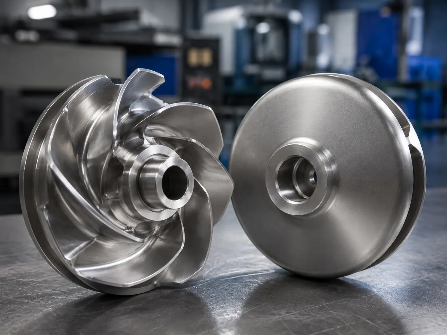
Clean impeller geometry shown as a manufacturing reference only; this image does not depict wear damage or establish a pump performance curve.
What to include in an impeller performance/RFQ review
If you are asking a manufacturer to quote a custom impeller after pump performance has changed, include more than the old part and a statement that “the pump has lost pressure.” Send:
- pump make/model or controlled assembly drawing and the exact impeller revision/diameter;
- original and current operating speed, required flow and total head, and the curve or test record used as baseline;
- liquid composition, temperature, density/viscosity, solids, particle size, and any corrosion or abrasion history;
- suction and discharge measurement locations, current flow/head readings, instrument details, valve/control state, and system changes;
- removed impeller photos with orientation, measured dimensions, damage map, and whether the sample has been repaired or modified;
- material grade and certificate requirement, critical machined features, clearances, runout, balance grade or specification, and reports required;
- quantity, prototype/production expectation, packaging, and export requirements.
For a proper hydraulic comparison, the pump OEM may also need to test or evaluate the complete pump, not only the impeller. A replacement wheel can be manufactured to approved requirements; a part-only quotation is not a guarantee that the installed pump will recover a particular flow, head, efficiency, or energy use.
Common questions about worn pump impellers and pump curves
Does a worn pump impeller always reduce flow?
No. Wear can reduce the pump’s head capability or efficiency, but the observed flow is set by the intersection of the pump and system curves, plus any controls and parallel equipment. A valve adjustment, speed change, process demand, or system resistance change can make measured flow rise, fall, or remain similar. Compare flow and total head at a documented speed and system condition before assigning the change to the impeller.
How does impeller wear affect pump head?
Vane-profile loss, rough surfaces, and internal leakage can reduce the energy delivered usefully to the liquid, so a worn pump may develop less head at a comparable flow and speed. The amount is design- and damage-specific. Use the correct pump curve, current measurements, and inspection findings; visual wear alone does not provide a reliable percentage or replacement threshold.
Can I estimate impeller wear from the pump curve alone?
The curve can show that measured performance differs from a baseline, but it cannot identify the cause by itself. A system change, wrong speed, blocked suction, instrument error, changed liquid properties, internal recirculation, or other pump damage may produce similar symptoms. Combine curve comparison with operating records and dimensional inspection, then ask the pump OEM or responsible engineer to determine the appropriate corrective action.
Is a worn wear ring the same as a worn impeller?
No. The wear ring or running clearance is a separate interface between rotating and stationary parts. Increased clearance can increase internal leakage and reduce useful delivery, while vane erosion changes the impeller’s hydraulic geometry. Both may occur together, but they require different measurements and replacement decisions. Compare the assembled clearance with the pump-specific drawing or OEM criterion; there is no universal clearance suitable for all pumps.
Does a worn impeller always use less power?
No. Power depends on flow, head, liquid properties, speed, efficiency, and the pump’s operating point. Wear may reduce efficiency, but the operating point can shift and motor load can move either way depending on design and system conditions. Review input power or electrical data with flow, total head, RPM, and the correct curve rather than using current alone as a wear indicator.
Can Matson determine the pump curve from my worn impeller?
No. Matson can review drawings, samples, photos, material requirements, critical dimensions, balancing, and manufacturing inspection for a custom impeller. A complete pump performance curve depends on the pump design and test conditions, and must be approved by the pump OEM or responsible engineering authority. Include the original curve and operating data in the RFQ so the replacement part can be tied to the approved configuration.
Final Thoughts
A worn impeller can contribute to reduced head and efficiency, but the pump curve and field operating point are not the same thing. Check the original curve, actual RPM, flow, total head, system condition, liquid, and clearances before deciding the part is responsible. Then compare the removed impeller with its approved geometry. Matson can review the manufacturing side of a suitable OEM replacement from a controlled drawing or sample.
If you are preparing a custom pump impeller RFQ, send Matson the drawing or sample, duty information, material, quantity, inspection, and balancing requirements.