Mixer impeller design considerations include the process objective, fluid properties, tank geometry, operating levels, circulation and shear requirements, mechanical loads, shaft connection, material, surface finish, and inspection criteria. Start by defining the result you need, then confirm the inputs that control geometry and manufacture. A blade name or motor rating alone is not enough. The approved design should connect a measurable process requirement to a drawing-controlled part before quotation or production.
Start with the result, not a blade shape
An impeller that fits the shaft can still be wrong for the mixing duty. Conversely, a promising mixing concept is not ready for manufacture until its dimensions, interfaces and acceptance requirements are defined.
The practical starting question is: what must be different in the tank after mixing, and how will you verify it? “Better mixing” does not answer that question. Neither does “a more powerful blade.”
A useful design brief identifies the required outcome, the operating envelope and the person responsible for approving performance. It might require an agreed concentration uniformity after a specified blending period, a defined suspension condition, or temperature uniformity at identified sampling locations. These are examples of acceptance categories, not suggested numerical targets.
For custom hardware, Matson’s mixer and agitator impellers page describes the product scope. This checklist addresses the information needed before making that hardware. It does not replace process trials, mixer-system engineering or equipment safety review.
Separate process design from manufacturing approval
Keep three approvals distinct:
- Process approval: the selected arrangement can deliver the required mixing result across the stated conditions.
- Mechanical approval: shaft, hub, drive, supports and clearances suit the operating loads and installation.
- Part approval: the manufactured impeller meets the controlled drawing, material, finish and inspection requirements.
One approval does not prove the others. A dimensional report does not establish blend time. A successful water trial does not establish performance in a viscous production batch. A material certificate does not confirm the finished hub fits your shaft.
Define the mixing duty and its acceptance condition
Different duties call for different evidence. Before comparing designs, identify whether the main task is bulk blending, solids suspension, dispersion, gas contacting or wall-side movement in a viscous product. A process can involve several tasks, but you should identify which one governs the design and which ones create constraints.
| Required duty | Inputs to establish | Acceptance question | Risk of an incomplete brief |
|---|---|---|---|
| Liquid blending | Composition, density, viscosity range, addition sequence, operating volume | Where and when is composition uniformity measured? | Visible surface movement is mistaken for whole-tank blending. |
| Solids suspension | Particle sizes, density, concentration, settling and restart conditions | Must solids remain off the floor, or meet a concentration profile? | A no-settling requirement is confused with uniform distribution. |
| Powder wetting or dispersion | Powder feed, wetting behavior, agglomerates, rheology, acceptable product damage | What residual agglomerate or product-quality criterion applies? | More local shear is specified without enough bulk circulation. |
| Gas-liquid contacting | Gas rate and entry location, liquid properties, pressure, foam limits | Which contacting result and stable operating condition must be demonstrated? | Ungassed performance is treated as proof under gas loading. |
| Viscous blending or wall-side movement | Rheology, temperature, vessel contour, clearance, scraping requirement | How are stagnant zones, deposits or temperature differences assessed? | Close clearance is copied without checking mechanical movement. |
| Shear-sensitive processing | Fragile component, permitted exposure, addition sequence, product acceptance test | What measurable change is unacceptable? | A low-shear label is treated as a product-protection guarantee. |
Specify normal operation and foreseeable transitions. Charging powder into a partially filled vessel, starting after solids have settled, or cooling a batch before discharge can govern a different condition from steady running.
Record fluid properties across the whole batch
Viscosity needs a condition and a measurement basis
“Viscosity: 5,000” is not a usable engineering input without units, temperature and measurement context. For a non-Newtonian material, apparent viscosity also depends on the applied shear conditions and potentially its processing history.
Send a viscosity range or rheology data representing charging, processing and discharge. Identify shear-thinning, shear-thickening, yield-stress or time-dependent behavior when known. If these properties have not been measured, flag the gap instead of substituting a guessed constant.
The highest reported viscosity is not automatically the only governing point. Low-viscosity charging can expose vortex or entrainment problems, while a later viscous stage creates a different circulation and load challenge. The engineering owner must evaluate the full sequence.
Density, solids and gas change the review
Record liquid density at relevant temperatures and distinguish liquid properties from slurry properties. For solids, state the particle-size distribution, particle density, concentration basis, abrasiveness, tendency to agglomerate, and whether fibrous material is present. “Ten percent solids” needs a mass or volume basis.
If restarting after settling is required, describe the settled condition and approved restart procedure. Do not assume a running-duty assessment covers startup in a compacted bed.
For gas-liquid service, provide gas flow, sparger location, pressure and allowable foaming or entrainment. For sensitive crystals, droplets or biological material, define the acceptance test rather than asking only for gentle mixing.
Review the tank as installed, not just its capacity
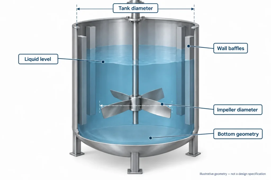
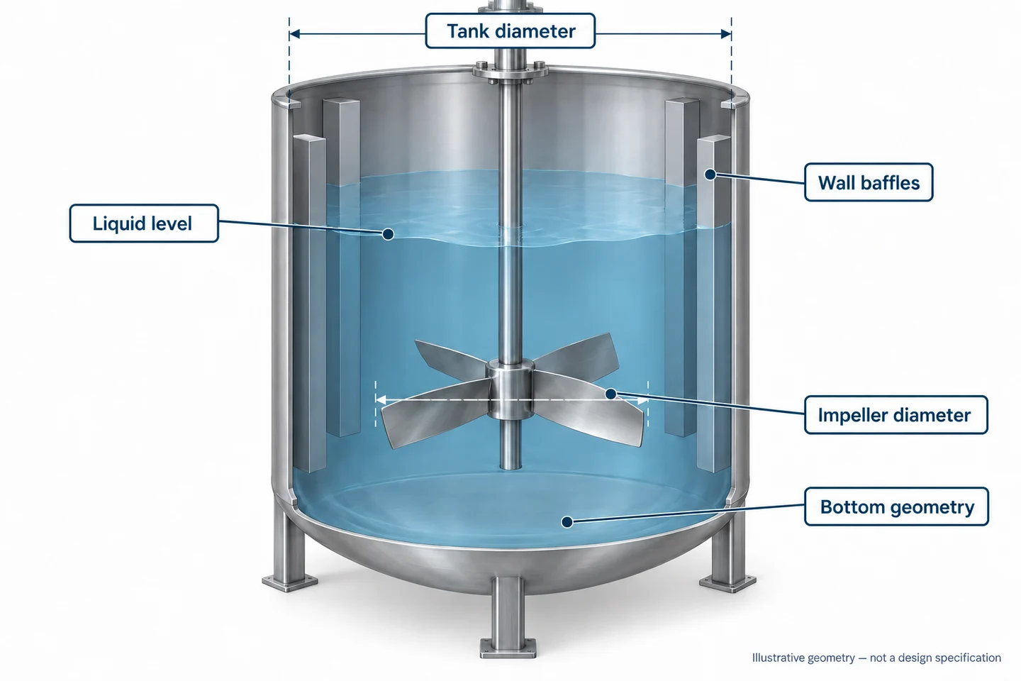
A nominal vessel volume does not define the mixing environment. Send the inside diameter, vessel height, bottom contour, normal liquid height, minimum operating level and maximum fill condition. Mark coils, dip pipes, probes, outlets, baffles and other internals on an arrangement drawing.
Diameter ratio and clearance are inputs, not universal rules
The impeller-to-tank diameter ratio describes the relationship between two dimensions. It does not independently select an impeller. Review it together with fluid behavior, blade form, liquid height, baffling, duty and drive constraints.
The University of Michigan’s mixing-correlation guidance explicitly cautions that correlations must match the impeller and tank geometry. A ratio used in one reference setup should not become an automatic production specification.
For clearance, state the measurement basis. A distance to the impeller center plane is different from the minimum physical gap between a blade edge and the vessel floor. The approved arrangement should identify both where needed, including allowances for assembly variation, operating movement and thermal effects. Do not specify a tight gap without the corresponding mechanical review.
Baffles, levels and installation access
For a center-mounted mixer in a low-viscosity liquid, the baffling arrangement affects how much motion becomes bulk swirling rather than the intended circulation. That does not mean every tank needs the same baffles. Offset, inclined, unbaffled and viscous arrangements require their own engineering basis.
Check minimum submergence and any operation during filling or draining. If the process permits the impeller to become partly exposed, have the equipment designer assess that condition explicitly.
Confirm that the finished part can enter the vessel and be assembled safely. Manway size, overhead space, lifting access and removable sections can influence the drawing even after the mixing concept is settled. The existing tank agitator impeller guide provides broader tank and manufacturing context.
Balance circulation, local shear and product protection
Axial, radial and mixed-flow descriptions help explain the direction of discharge near an impeller. They are not complete performance specifications. The vessel and its internals affect the resulting circulation.
If you need bulk blending, ask how the arrangement exchanges material throughout the working volume. If you need dispersion, ask how material reaches the high-shear region and how the rest of the batch circulates. If you need to protect a fragile ingredient, define acceptable product change and the relevant exposure conditions.
The SPX FLOW impeller technology overview distinguishes the flow pattern from energy imparted to the fluid and relates both to the process result. That distinction is useful when reviewing a design brief; the supplier’s process-engineering capabilities should not be assumed to belong to Matson.
Do not select a blade by appearance or rank impellers with a single “efficiency” label. Compare evidence for the actual task. For a type-by-type introduction, use the existing agitator impeller types article; this checklist focuses on what must be established before choosing and manufacturing one.
Check power, torque and speed without confusing their roles
Motor nameplate power is not the same as power absorbed by the impeller. Available output also needs the drive arrangement, losses and operating condition to be considered. Two systems with the same motor power but different shaft speeds can impose different torque requirements.
For a steady rotating shaft, the mechanical relationship is:
Shaft torque = transmitted shaft power ÷ angular speed.
With power in watts and speed N in revolutions per second, torque in newton-metres is P ÷ (2πN). Use transmitted shaft power at the condition being reviewed, not an unexplained motor rating. This relationship alone does not cover startup, overload or fatigue.
For a defined impeller and condition, power number is expressed as Np = P ÷ (ρN³D⁵), with consistent units. The coefficient requires an appropriate geometry and flow-regime basis. It is not a universal constant for every blade that has the same general name.
ProQuip’s impeller design and performance paper discusses diameter, speed, geometry and fluid properties as power inputs, and warns against using pumping capacity as the only mixer comparison. Ask what conditions and measurement basis support any quoted coefficient or flow figure.
What to request from the mechanical engineering owner
Obtain the approved operating speed range, rotation direction, transmitted loads, startup condition, mounting arrangement and restrictions on the shaft or drive. Clarify whether blade and hub loads, shaft bending, critical-speed behavior, fatigue and support loads have been assessed for the complete assembly.
A balanced impeller does not resolve an unsuitable shaft support or resonance condition. A larger blade is not a harmless substitution. Changes to diameter, pitch, speed, material mass or stage arrangement should return to the responsible engineering owner before production.
Keep detailed sizing and scale-up calculations outside a general procurement checklist. If the design is being transferred from pilot scale, require a documented scale-up basis and a plan to verify the production result.
Put functional geometry and the shaft connection on the drawing
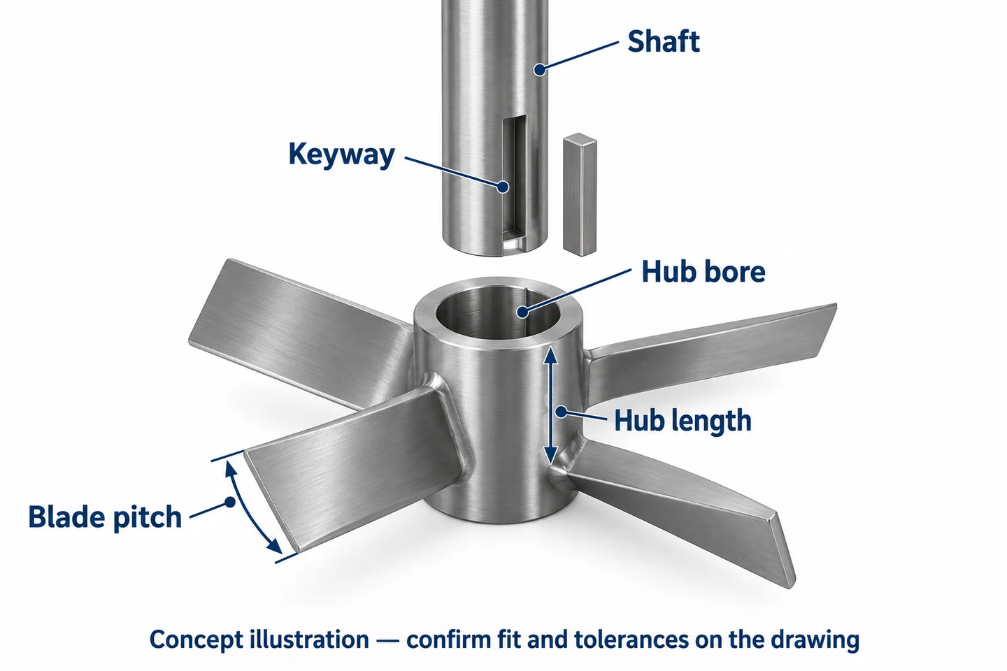
Once the engineering concept is approved, translate it into inspectable features. Specify outside diameter, blade count, blade width and thickness, pitch reference, profile, hub position and overall envelope. Define rotation direction from a named viewing direction, such as looking down from the drive, and state intended pumping direction separately.
“Clockwise” without a viewpoint is ambiguous. A photograph without a reference plane cannot establish blade pitch. A 3D model without critical tolerances cannot settle every acceptance question.
The connection must transfer load and remain serviceable
Confirm whether the connection is keyed, clamped, split, flanged, welded or otherwise specified. Record the mating shaft dimensions, bore fit, key and keyway requirements, hub length, axial position, retention method and any bolt details.
For a split hub or removable blade assembly, specify the assembly configuration used for inspection. If matched components must stay together, define identification and packing requirements. For a welded shaft assembly, agree which dimensions will be checked after welding and any subsequent machining.
Fit and retention should be approved for the actual loads and environment. A set screw, key or clamp should not be added as a supplier assumption because the RFQ lacks a connection detail.
A worn sample is evidence, not the design authority
Mark rubbed edges, bent blades, enlarged bores, repaired welds and corroded areas. These features can distort the dimensions you are trying to recover. Separate directly measured dimensions from reconstructed or engineering-approved ones.
If the sample and drawing disagree, identify which controls each feature before quotation. A supplier should not silently reproduce damage or choose the more convenient dimension. For repeat orders, use one approved revision rather than a mixture of old drawings, photos and email changes.
Select material and finish from exposure and acceptance requirements
Specify the material grade and governing material standard, not merely “stainless steel.” Review liquid composition, concentration, contaminants, temperature, cleaning chemicals, abrasion and any contamination restrictions. Blade, hub, weld filler and fasteners should be addressed where their exposure differs.
Do not assume a grade suitable for the normal batch is suitable for the cleaning cycle. Material substitution needs approval against the full exposure and mechanical requirements, not only an equivalent-looking grade name.
For finish, distinguish visual appearance from measured acceptance. Identify where roughness requirements apply, how they are measured, and which weld transitions, edges or crevices need attention. Polishing, passivation and electropolishing are different requirements and should not be treated as interchangeable words for “smooth.”
A shiny surface does not establish a hygienic design. If cleanability, food-contact requirements or specific compliance documents matter, state them explicitly and confirm project suitability before ordering. Do not infer regulatory compliance from an image or a material designation.
Plan manufacture around the features that matter
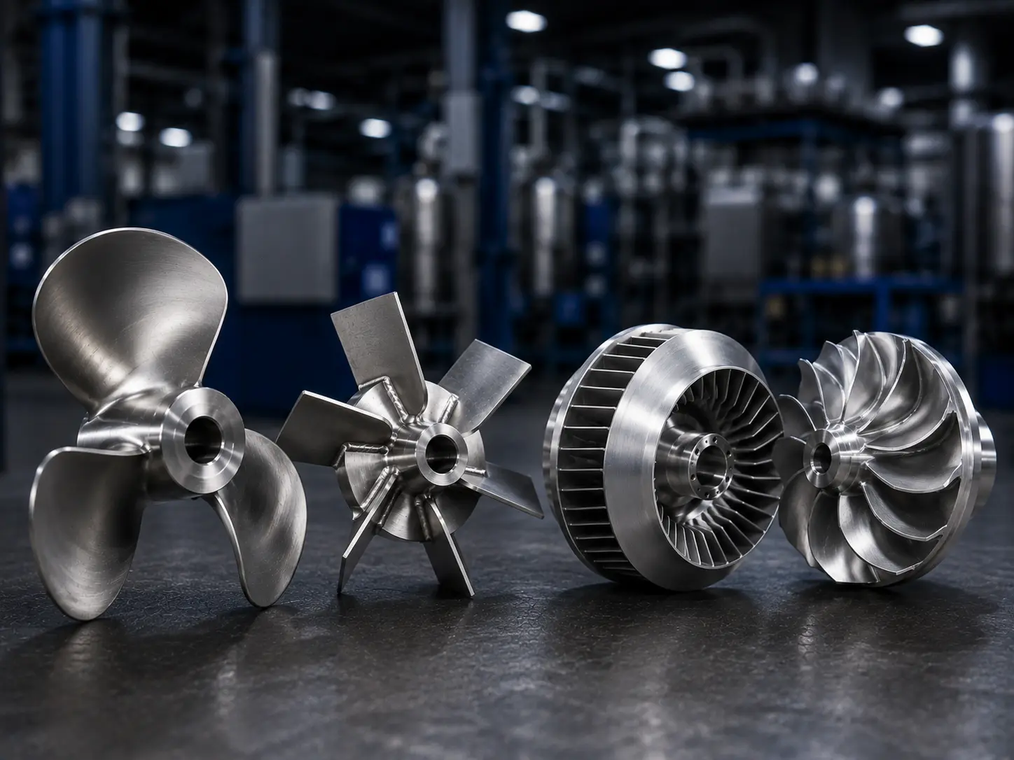
Fabrication, casting and machining are not interchangeable price options when they change geometry, material condition or acceptance. Matson’s impeller manufacturing capabilities provide the relevant process context; the actual route needs project-specific review.
| Route under review | Drawing and process questions | Acceptance to define |
|---|---|---|
| Fabricated blade and hub assembly | Blade forming, weld detail, fixture references, distortion and cleanup | Finished pitch/profile, weld acceptance, bore condition and runout after the final relevant operation |
| Cast blank with finish machining | Alloy specification, casting geometry, machining stock and functional datums | Material documents, required casting examination and finished interface dimensions |
| Machined component | Stock specification, model revision, critical profile and accessible measurement points | Profile/size tolerances, finish, datum relationships and dimensional evidence |
| Modular or removable assembly | Joint details, fasteners, orientation, identification and installation access | Assembled envelope, matched-part control, inspection setup and reassembly instructions |
The lowest process price is not necessarily the lowest accepted-part cost. Compare the same material, finished geometry, examination, reporting and quantity basis. If a proposed route changes blade thickness, weld form or finished mass, return the change for engineering approval.
Inspection planning should identify a functional datum, often based on the approved shaft interface, and distinguish size measurements from geometric relationships. “Check concentricity” is not enough if the drawing actually requires radial or axial runout under a specified mounting setup.
Balance requirements should identify the applicable specification, operating condition, rotor configuration and report expectations when required. Do not assign a universal balance grade or tolerance from this article. Agree whether keys, fasteners and removable parts are included and whether verification occurs after the last operation capable of changing the result.
Use an RFQ release checklist, not a collection of assumptions
Before sending the enquiry, classify each item as confirmed, pending engineering approval or unavailable. A supplier can review an incomplete brief, but a preliminary estimate should not be mistaken for a production release.
| Information group | Send or confirm | Reason to hold production release |
|---|---|---|
| Process basis | Duty, measurable result, fluid-property range, operating sequence and approval owner | Mixing performance or governing condition has not been approved. |
| Installed arrangement | Tank drawing, liquid levels, baffles, internals, stage positions and installation access | Interference, exposure or clearance basis remains unresolved. |
| Controlled part definition | 2D/3D revision, blade geometry, rotation viewpoint, hub connection and retention | Model, drawing and sample contradict one another. |
| Material and finish | Grade/standard, certificates, weld and surface requirements, exposure conditions | A substitution or finish requirement lacks approval. |
| Mechanical inputs | Speed range, approved loads, assembly configuration and relevant restrictions | Geometry changes have not been reviewed against the shaft/drive. |
| Part acceptance | Critical features, tolerances, measurement setup, examination, balance/runout and reports | “Same as sample” or “good quality” is the only acceptance instruction. |
| Commercial and repeat-order basis | Quantity, sample approval, batch schedule, identification, packaging and change notification | Quote exclusions or drawing-revision ownership are unclear. |
For quotation comparison, ask each supplier to list exclusions and unresolved inputs. A lower quotation that excludes final machining, material documents or specified inspection is not the same scope. Keep any accepted deviation attached to the drawing revision and purchase requirement.
Know when a design change needs another review
Revisit the approved basis when the fluid formulation, solids loading, temperature, operating level, blade geometry, speed, stage location, shaft connection or vessel internals change. A manufacturing route or material substitution can also require review if it affects the approved part.
Three common shortcuts deserve particular caution:
- Keeping motor power while changing the impeller: absorbed power and load do not stay fixed just because the motor does.
- Copying a laboratory blade into a production vessel: geometric resemblance does not establish equivalent mixing or mechanical behavior.
- Accepting a part by photograph: appearance cannot verify bore fit, blade pitch, material traceability or defined runout.
Agree who approves deviations before a supplier encounters them. For repeat orders, preserve the approved drawing, reports and accepted first-article record as the baseline. A change should have a disposition, not disappear into correspondence.
How Matson supports a defined custom impeller project
Matson manufactures custom industrial mixer and agitator impellers from reviewed drawings, models, samples and specifications. For suitable projects, the manufacturing review can address material, route, machining, surface treatment, dimensional inspection, balancing requirements and export packing.
The useful next step is to send a controlled part definition with its operating context. If process performance is not yet established, identify that separately. Matson’s manufacturing review should not be presented as proof of blend time, suspension quality, scale-up or complete-mixer safety.
Specific questions before ordering a mixer impeller
What are the most important mixer impeller design considerations before an RFQ?
Start with the required process result, fluid-property range and installed tank arrangement. Then confirm approved geometry, speed, loads, shaft connection, material, finish and inspection criteria. The priority is resolving inputs that change the design, not collecting the most documents. If process approval is missing, describe the enquiry as preliminary and separate engineering decisions from the manufacturer’s quotation assumptions.
Is tank volume enough to select impeller diameter?
No. Equal-volume vessels can have different diameters, liquid heights, bottom contours and internals. Impeller diameter must be assessed with blade geometry, fluid behavior, operating level, baffling, process duty and drive constraints. Provide the arrangement drawing rather than asking the supplier to infer these features from capacity. Any proposed diameter change should return to the responsible process and mechanical engineering owners.
What viscosity information should I provide for a shear-thinning liquid?
Provide viscosity or rheology measurements with units, temperature and the measurement conditions, ideally covering relevant shear rates and batch stages. Identify any yield stress or time-dependent behavior if known. One apparent-viscosity value does not describe every operating condition. If data are unavailable, make that limitation visible so the design owner can decide what testing is required before approving the impeller.
Can I replace a hydrofoil with a pitched-blade turbine of the same diameter?
Not on diameter alone. The change can affect power demand, local shear, circulation, axial loading and the finished part’s mass and connection requirements. Confirm performance and mechanical suitability for the actual vessel and liquid before approving the substitution. A manufacturer can quote the revised drawing, but matching outside diameter does not establish that the new geometry is an equivalent process component.
Does an accepted balance report prove the agitator will run without vibration?
No. A balance report addresses the defined rotor configuration and acceptance requirement. Installed vibration also involves shaft geometry, supports, alignment, critical-speed behavior, loads and operating conditions. Check that the report matches the supplied assembly and any included keys or fasteners. Do not use a part-level balance result to close unresolved system-level mechanical questions or to promise vibration-free operation.
Which dimensions are most important when reproducing a worn mixer impeller?
Confirm the shaft interface, hub location, finished envelope, blade profile, pitch and rotation convention. Mark damage and separate measured dimensions from reconstructed ones. Rubbed edges, an enlarged bore or a repaired blade can make the sample misleading. Use an approved reconstruction drawing with agreed critical tolerances before production, rather than allowing each supplier to interpret the worn part independently.
How should polishing and passivation be specified for a mixer impeller?
Identify the surfaces covered, required roughness where applicable, weld cleanup, edge condition, treatment and documentation. State the cleaning environment and any specific compliance requirement. Polishing controls surface condition, while passivation is a separate treatment requirement; neither should be represented by a vague request for sanitary finish. Confirm inspection methods and acceptance with the supplier before selecting the manufacturing route.
Can Matson manufacture the impeller if the process design is already approved?
Yes, suitable custom mixer and agitator impeller projects can be reviewed from controlled drawings, models or properly assessed samples. Send the material specification, quantity, shaft details, operating context, finish and inspection requirements. Matson can review manufacturing scope before quotation. Keep process-performance approval and complete-mixer engineering with the responsible owner, and identify any proposed manufacturing deviation for approval before release.
Final Thoughts
A useful mixer impeller design checklist connects the required mixing result to approved geometry, mechanical interfaces and measurable part acceptance. Resolve the process conditions first, then freeze the details a manufacturer must control. Matson can review suitable custom impeller drawings, materials, manufacturing routes and inspection needs. Clear ownership of unresolved inputs makes quotations more comparable and helps keep approved requirements intact through sample approval and repeat orders.
Ready to request a manufacturing review? Send your approved drawing or model, tank arrangement, fluid conditions, shaft connection, material grade, quantity and inspection requirements through the Matson custom impeller RFQ page. Mark any pending engineering decisions so they can be separated from the quotation scope.