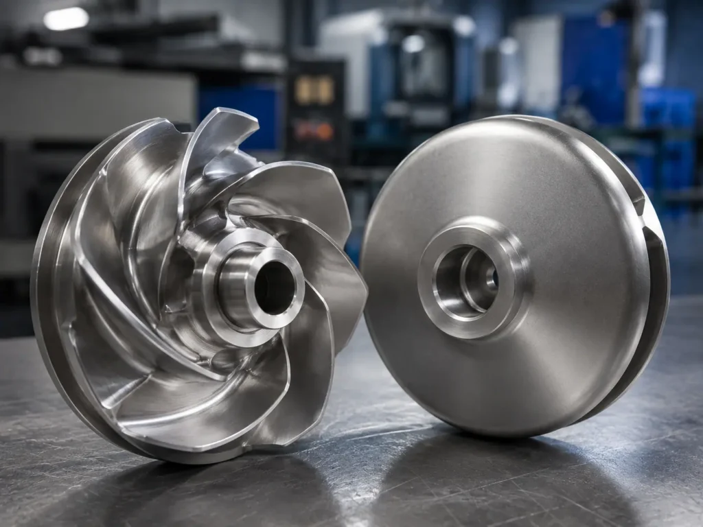
The main propeller vs impeller difference is scope: a propeller usually means an open-bladed rotor that drives fluid mainly along its shaft axis or produces thrust, while impeller is the broader term for a rotating component that transfers energy to liquid or gas. The terms overlap in axial-flow pumps and mixers, so an industrial RFQ should identify the host equipment, flow direction, geometry and shaft interface instead of relying on the name alone.
Is a propeller a type of impeller?
In many industrial pump and mixing contexts, yes. A propeller-style rotor can be classified as an axial-flow impeller. It has a hub with a small number of pitched blades and moves fluid mainly parallel to the shaft. The term “impeller,” however, also covers radial-flow, mixed-flow, centrifugal, turbine, hydrofoil, paddle, anchor and other rotating geometries.
That is why the words are not clean opposites. KSB’s propeller-pump reference describes a ship propeller, propeller-type mixer and propeller pump as sharing an axial-flow impeller principle. Its broader impeller reference includes radial, mixed-flow and axial forms.
For sourcing, the useful question is not “Which word is universally correct?” It is “What component does this drawing define, what machine contains it, and what flow or process duty must the approved geometry support?”
Propeller vs impeller comparison
The table below uses common industrial meanings. Individual OEMs and industries may apply the terminology differently, so the approved drawing and equipment documentation remain the final reference.
| Comparison point | Propeller | Impeller | RFQ implication |
|---|---|---|---|
| Term scope | A more specific open-bladed rotor form or propulsion component. | A broad family of rotating fluid-energy-transfer components. | State the equipment type and OEM terminology instead of substituting names. |
| Typical flow direction | Mainly axial, along the shaft direction. | May be axial, radial, mixed or application-specific. | Provide required pumping or flow direction and rotation viewing side. |
| Blade structure | Usually a low blade count with pitched, often twisted blades around a hub. | May use vanes, blades, discs, shrouds, paddles, ribbons or enclosed passages. | Send the full blade or vane profile, not only diameter and blade count. |
| Common equipment context | Propulsion, axial-flow pumps, circulation and propeller-style mixers. | Centrifugal pumps, fans, blowers, compressors, mixers and agitators. | Name the host machine, casing or tank and relevant mating parts. |
| Pressure, flow or thrust role | Often selected to create axial flow or thrust. | May build pump head, create airflow, circulate a tank or perform another mixing duty. | Supply the approved duty data; do not expect the name to define performance. |
| Surrounding structure | May operate in an open medium, vessel or tubular casing. | May operate inside a volute, diffuser, housing, duct, tank or open vessel. | Include casing, clearance, tank or installation interfaces when they affect fit. |
| Manufacturing focus | Blade pitch, twist, thickness, hub attachment and tip condition. | Depends on type: eye, vane passage, shroud, outlet, disc, hub, welds and clearances may matter. | Define functional surfaces, material, finish, inspection and balance condition. |
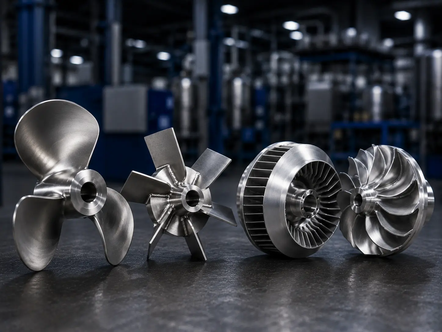
Flow direction is the clearest first distinction
A conventional propeller accelerates fluid through the plane of rotation and produces an axial reaction. In industrial mixing, the same basic geometry is used to circulate liquid upward or downward in a tank. In an axial-flow pump, the liquid also moves mainly along the shaft direction.
An impeller does not have one universal flow direction. A radial centrifugal pump impeller receives liquid near the shaft axis and directs it outward. A mixed-flow impeller combines axial and radial components. A mixer impeller may create axial circulation, radial discharge, high shear near a disc or close-clearance movement near a vessel wall.
Flow direction is therefore more useful than appearance alone. A three-bladed rotor can look like a propeller, but the required pitch, pumping direction, diameter, hub ratio, clearance and speed come from its approved equipment design. Reversing the same part does not automatically reverse its duty correctly. Blade camber, leading and trailing edges, shaft threads and hub retention can all be directional.
The flow pattern also affects the information a buyer must send. An axial-flow component needs clear blade pitch and tip-clearance references. A radial pump impeller needs inlet-eye, outlet-width, casing and wear-interface information. A tank mixer needs vessel geometry, baffles, liquid properties, solids and the intended circulation or dispersion duty.
Equipment context changes what the words mean
Propeller pumps
In a propeller pump, the rotating element is both a propeller and an impeller. It is normally discussed as an axial-flow or mixed-flow pump component. The casing, inlet approach, blade pitch, hub and downstream guide structure are part of the system definition. A supplier should not replace the approved propeller with a radial centrifugal impeller simply because both are called pump impellers.
Tank mixers and agitators
A propeller is one type within the wider mixer-impeller family. Other mixer impellers include pitched-blade turbines, Rushton turbines, hydrofoils, anchors, paddles, helical ribbons and dispersion blades. ProQuip’s industrial tank-agitator design paper uses flow pattern as a primary way to classify mixer impellers, which is more useful than treating every rotating mixer blade as the same propeller.
The mixer and agitator impeller page is the commercial destination for custom industrial mixing components. This comparison article only clarifies terminology and RFQ decisions.
Centrifugal pumps
Most centrifugal pump discussions use “impeller,” not “propeller,” because the geometry transfers liquid from an inlet eye through radial or mixed-flow passages. Open, semi-open and closed impellers may use vanes and shrouds that do not resemble a conventional propeller. The custom pump impeller page owns the product and quotation intent for those components.
Fans, blowers and compressors
These machines normally use terms such as impeller, fan wheel, blower wheel or rotor. Some axial fans have propeller-like blades, but calling every fan impeller a propeller can hide the housing, inlet, wheel width, blade direction, balance and speed requirements. For commercial fan-wheel sourcing, use the fan and blower impeller page rather than this informational comparison.
Propulsion equipment
Marine and aircraft propellers use the word in a propulsion sense. They create thrust and have design, certification, material, fatigue and service requirements outside Matson’s current industrial impeller positioning. This article does not target boat-propeller replacement, aircraft propellers, outboard parts or consumer repair.
Geometry differences buyers should put on the drawing
A propeller RFQ often needs more than diameter and blade count. Blade pitch may change from hub to tip. The blade section can twist and vary in thickness. Leading-edge, trailing-edge, pressure-side and suction-side definitions must agree with the rotation direction. The hub may use a straight bore, taper, key, spline, thread, clamp or flange.
An impeller RFQ depends on the exact type. A centrifugal pump impeller can add an eye, front and rear shrouds, enclosed passages, wear-ring seats and an outlet width. A fan wheel can add a backplate, inlet ring and many repeated blades. A mixer turbine can add a disc, welded blades and a long-shaft connection. An anchor or ribbon can depend on vessel-wall clearance and fabrication roundness.
Do not reduce either component to a silhouette. A front photograph may show blade count but not pitch, twist, passage width, hub fit or axial position. A side photograph may show pitch direction but hide damage on the opposite face. If the part is made from a worn sample, mark bent tips, ground edges, repairs, corrosion and rubbed areas so the supplier does not copy service damage as nominal geometry.
RFQ decision table: what to confirm before quotation
| RFQ item | For a propeller-style component | For another impeller type | Buyer confirmation |
|---|---|---|---|
| Host equipment | Axial pump, tank mixer, circulation device or propulsion system. | Pump, fan, blower, compressor, mixer or custom machine. | Name the machine and provide assembly or interface context. |
| Flow and duty | Axial pumping direction, thrust or circulation duty. | Required head, flow, airflow, pressure or mixing duty as applicable. | Use approved equipment data; the manufacturer should not infer performance from appearance. |
| Rotation convention | Clockwise/counterclockwise with viewing side and pumping direction. | Rotation plus inlet/outlet, suction side, drive side or shaft-end reference. | Put arrows and reference view on the drawing. |
| Blade or vane geometry | Blade count, pitch, twist, profile, thickness, tip diameter and hub ratio. | Vane count, inlet/outlet angles, passage, shroud, disc or blade dimensions. | Provide 3D geometry where a 2D drawing cannot define the surface. |
| Mounting interface | Bore, taper, key, thread, spline, clamp, flange or blade trunnion. | Bore, keyway, hub faces, taper, bolt pattern or welded shaft connection. | State fits, datums and mating-part dimensions. |
| Material and finish | Fluid/gas, corrosion, temperature, solids and surface requirements. | Same service data plus as-cast, machined, polished, coated or welded zones. | Specify grade and acceptance; do not use “stainless” alone. |
| Inspection and balance | Pitch, blade tracking, tip condition, runout and balance configuration. | Dimensions, passages, runout, welds, NDT and dynamic balance as required. | State the inspection stage, report format and assembled condition. |
Manufacturing routes are selected by geometry, not by the label
Propeller-style and other impeller components can be cast, machined, fabricated or made through a combined route. The word on the purchase order does not decide the process.
Casting can form curved blades, hubs and passages near net shape. The review must address material, pattern or tooling, section thickness, allowance, distortion, internal accessibility and finish machining. CNC machining can establish the bore, taper, hub faces and other controlled interfaces; complex free-form blades may also require multi-axis access. Fabrication suits selected mixer, fan and custom rotor geometries but adds joint design, welding sequence, distortion and post-weld inspection questions.
For either component, balance is the last result of controlled geometry and mass distribution, not a substitute for them. Blade pitch errors, unequal thickness, a mislocated hub or local weld buildup can remain functional problems even if material is removed elsewhere to reach a balance result.
Matson’s impeller manufacturing capabilities include investment casting, sand casting, 3-axis and 5-axis CNC machining, surface treatment, dimensional inspection and dynamic balancing for suitable projects. Final process selection must be confirmed against the drawing, material, size, quantity and acceptance requirements.
Common naming mistakes in OEM sourcing
The first mistake is changing the drawing name without changing the definition. If the OEM calls the part an “axial impeller,” a supplier should not relabel it “propeller” and assume the documentation still matches. Preserve the controlled part name and add a plain-language description only for clarification.
The second mistake is treating “propeller” as proof of marine service. Industrial mixers and propeller pumps also use the term. Conversely, a boat propeller is not automatically within an industrial impeller supplier’s capability simply because both components have blades and a hub.
The third mistake is using “impeller” as if it defined one geometry. A request for “300 mm stainless impeller” leaves the supplier without the vane form, hub, rotation, material grade, host equipment, operating condition, tolerance, finish or balance requirement. It is a search phrase, not a production specification.
Finally, do not choose a replacement type from a comparison chart alone. Changing a propeller-style mixer rotor to a hydrofoil, or an axial pump propeller to another impeller form, changes the hydraulic or process design. Matson can review manufacturing feasibility against supplied data; the OEM or responsible engineering owner must approve performance changes.
What to send for a propeller or impeller RFQ
You will get a more useful quotation if the package answers the following points:
- controlled part name, part number, drawing number and revision;
- host equipment and assembly position;
- approved 2D drawing and 3D model where available;
- complete sample with marked wear, repair or modification zones if no drawing exists;
- outside diameter, blade or vane count, pitch/profile and critical clearances;
- hub, bore, keyway, taper, thread, flange or shaft-connection details;
- rotation direction, viewing side and intended pumping direction;
- material grade and material-certificate requirement;
- fluid or gas, temperature, solids, corrosion, abrasion and cleaning conditions;
- operating speed and required balancing condition;
- machined, welded, polished, passivated, coated and protected surfaces;
- dimensional, NDT, runout, balance and report requirements;
- prototype quantity, batch quantity and expected repeat demand.
If you only have photographs, start with front, back, side, hub, bore, blade-root and blade-tip views next to a scale. Photographs can start a feasibility review, but they should not be treated as a full release package for complex blade geometry.
How Matson supports suitable industrial projects
Matson focuses on custom industrial impellers for pumps, fans, blowers, selected compressor projects, mixers, agitators and non-standard OEM equipment. Propeller-style mixer or pump components can be reviewed when the drawing, model, material, interfaces, application condition and quality requirements are available.
The commercial objective is not to sell a generic propeller from a catalogue. It is to determine whether a defined industrial rotating component fits Matson’s casting, machining, fabrication, surface-treatment, inspection and balancing scope. Marine propulsion propellers, aircraft propellers, rubber outboard impellers and consumer replacement parts remain outside this article’s business target.
Common questions about propellers and impellers
What is the main difference between a propeller and an impeller?
A propeller usually refers to an open-bladed rotor that produces thrust or mainly axial fluid movement. Impeller is a broader term for rotating components that transfer energy to liquid or gas. An impeller may be axial, radial, mixed-flow or process-specific. In an axial-flow pump or propeller mixer, the same component can reasonably be described as both a propeller and an impeller.
Is a mixer propeller also an impeller?
Yes. In industrial mixing, a propeller is one type of mixer impeller, commonly associated with axial circulation. Other mixer impellers include hydrofoils, pitched-blade turbines, Rushton turbines, anchors, paddles, helical ribbons and dispersion blades. The correct selection depends on the approved mixer design, tank, viscosity, solids, duty and speed; the name alone does not establish performance.
Why are centrifugal pump impellers not usually called propellers?
Centrifugal pump impellers commonly receive liquid near an eye and direct it radially or diagonally through vane passages toward the casing. Their shrouds, outlets and flow path differ from the conventional open, axial-flow propeller form. Some axial-flow and mixed-flow pump rotors are called propellers, but that terminology should not be extended to every centrifugal pump impeller.
Can a propeller and an impeller use the same manufacturing process?
They can share processes such as casting, CNC machining, fabrication, polishing, inspection and balancing, but the route depends on geometry and requirements. A propeller-style blade may emphasize pitch, twist and tip tracking, while a shrouded pump impeller introduces enclosed passages and internal inspection. Process capability should be reviewed against the drawing, material, size, quantity and acceptance criteria.
What information prevents rotation-direction mistakes?
State clockwise or counterclockwise rotation together with the exact viewing side, such as drive end, shaft end, suction side or hub side. Add a rotation arrow and the intended pumping direction to the drawing. Photographs alone can be misleading when a part is turned over. Thread direction, blade pitch, leading/trailing edges and hub retention should agree with the stated convention.
Does Matson manufacture marine or aircraft propellers?
Matson’s confirmed positioning is custom industrial impellers for pumps, fans, blowers, selected compressor projects, mixers, agitators and OEM equipment. This article does not offer aircraft propellers, ship-propulsion propellers, outboard propellers or consumer marine replacement parts. A propeller-style industrial pump or mixer component can be reviewed only against its drawing, material, interfaces, operating condition and quality requirements.
Final Thoughts
Propeller and impeller are overlapping engineering terms, not interchangeable production specifications. Start with the host equipment and required flow direction, then control the blade or vane geometry, hub interface, material, finish, inspection and balance condition. When those details are clear, Matson can review whether a propeller-style or other industrial impeller fits an appropriate manufacturing route without assuming responsibility for unapproved performance changes.
Send Matson your industrial propeller or impeller drawing for review. Include the host equipment, 2D/3D data, material, rotation convention, application condition, quantity, inspection and balancing requirements.