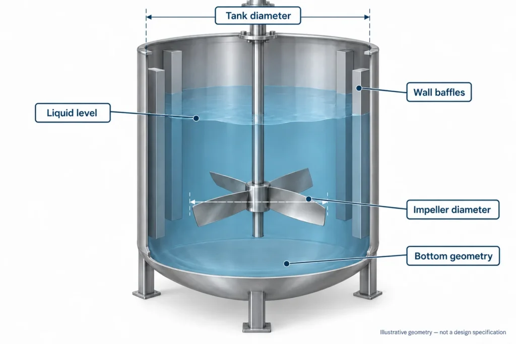
A mixing impeller for shear-sensitive materials must circulate the batch while keeping product damage within an agreed limit. Low speed alone is not enough: diameter, blade geometry, local clearances, fluid properties and exposure time also matter. Start by defining what must remain intact, then confirm that the selected impeller meets both the mixing target and the product-quality target. Release the manufacturing drawing only after those requirements are reconciled.
What does “shear-sensitive” mean in your process?
Shear-sensitive mixing is a product-integrity problem, not simply a mixer-speed category. The concern is whether mechanical exposure changes a property that matters to the next process step or the finished product.
That property needs a measurable definition. A crystal suspension might require a controlled particle-size distribution. A formulated liquid might need viscosity measured at a specified temperature after an agreed recovery period. A blend containing soft inclusions might require their size or appearance to remain within an acceptance limit.
Do not assume every viscosity reduction proves permanent damage. Shear thinning describes lower apparent viscosity under shear; it does not, by itself, demonstrate irreversible degradation. Some materials recover after resting, while others undergo changes that the process cannot reverse. Use the material supplier’s information and a suitable test method to establish which behavior you are dealing with.
For drawing-based procurement, separate two approvals. The process owner approves product quality and mixing performance. The component manufacturer confirms how the approved impeller geometry, material and inspection requirements will be delivered. Matson’s custom mixer and agitator impellers support that manufacturing handoff, rather than replacing process qualification.
Why low speed is not a complete specification
Diameter changes the meaning of rpm
Blade-tip speed is the distance traveled by the outer tip per unit time:
Tip speed = π × D × N, where D is impeller diameter in meters and N is rotational speed in revolutions per second. Divide rpm by 60 before using this equation.
For illustration only, a 0.30 m impeller at 120 rpm has a tip speed of about 1.88 m/s. A 0.60 m impeller at 60 rpm has the same calculated tip speed. These are hypothetical numbers, not recommended operating points or safe limits for a particular material.
The example shows why an rpm limit cannot travel unchanged between different diameters. It does not establish equivalent circulation, local shear or product damage. Blade profile, vessel arrangement and fluid behavior remain different inputs.
Local conditions matter more than a single average
Shear rate describes how quickly fluid velocity changes across distance. The highest exposure is not necessarily represented by the average power delivered to the vessel. Blade edges, wakes and close-clearance regions deserve attention, especially where particles can encounter moving and stationary surfaces.
In a simple narrow-gap model, velocity difference divided by gap estimates a shear rate. A working mixing tank has a much more complex flow field. Do not turn that simplified relationship into a universal calculation for every blade or claim that a drawing proves a safe shear rate.
SPX FLOW’s Lightnin impeller brochure describes selected hydrofoil designs as emphasizing circulation with reduced fluid shear. That is a useful selection principle, not proof that any hydrofoil at any speed protects your material.
Longer mixing is not automatically gentler
Reducing speed can leave the batch circulating poorly, requiring a longer run to reach the same endpoint. Product then experiences more time in the mixing system. Whether that is better or worse must be measured for the material and duty.
Review exposure across the complete route: initial incorporation, tank mixing, holding, recirculation, transfer and any downstream restrictions. A gentle tank impeller cannot eliminate damage caused elsewhere. Avoid changing several steps at once during diagnosis, because the results become difficult to attribute.
Start with the application and its acceptance test
The following scenarios are decision examples, not Matson customer cases or guaranteed application capabilities. Use them to make the phrase “gentle mixing” specific enough to test.
| Application scenario | Property to protect | Mixing requirement that still matters | What to confirm before selection |
|---|---|---|---|
| Fragile crystals or granules in liquid | Particle size, shape and acceptable fines | Required suspension condition and concentration uniformity | Particle distribution, density, solids fraction, attrition test and sampling method |
| Polymer-containing solution or structured liquid | Specified rheology after an agreed conditioning period | Additive distribution without stagnant regions | Viscosity versus temperature/shear, recovery behavior and evidence of irreversible change |
| Preformed emulsion during a later blending stage | Approved droplet distribution and stability attributes | Uniform incorporation of the remaining ingredients | Process stage, ingredient sequence, droplet measurement and hold conditions |
| Liquid containing soft inclusions | Inclusion integrity and acceptable fragment content | Distribution throughout the batch and during discharge | Inclusion size/strength, sampling bias and inspection method |
| Flocculated suspension after floc formation | Defined floc condition or downstream separation result | Enough circulation for the intended holding or transfer step | Stage-specific requirements and a representative separation/quality test |
If you specify only “no damage,” the supplier has no acceptance threshold to manufacture or inspect against. State the reference condition, measurement method and allowed change. The process team must decide these values; they should not be invented during quotation.
Applications involving living cells, biological activity or regulated product claims need specialist process validation. A metal impeller drawing and material certificate cannot establish those outcomes.
Which impeller types belong on the shortlist?
For a relatively mobile liquid that needs bulk blending, an axial-flow hydrofoil is a sensible candidate to evaluate. A pitched-blade turbine can also be considered where the duty and approved arrangement support it. More viscous materials can require a different circulation strategy, including close-clearance equipment.
The hydrofoil impeller guide covers blade-profile and manufacturing detail. Here the question is narrower: does the proposed geometry achieve the required distribution without exceeding your product-damage limit?
| Candidate | Why evaluate it | Where caution is needed | Evidence to request |
|---|---|---|---|
| Axial-flow hydrofoil | Bulk circulation with an emphasis on pumping rather than intense local processing | Rheology, gas loading and installed geometry can change suitability | Identified geometry, relevant operating conditions and product-quality trial |
| Pitched-blade turbine | General blending or suspension duties with a defined tank arrangement | The same rpm as another design does not imply the same shear exposure | Blade angle/profile, pumping direction and matched-endpoint comparison |
| Anchor or helical ribbon | Movement of viscous material where small impellers do not provide adequate turnover | Local gaps, torque, particles and vessel fit need careful review | Rheology, clearance drawing, mechanical approval and representative mixing test |
| Radial turbine or dispersion-oriented blade | Evaluate only when the process genuinely requires its local mixing action | Intentional dispersion can conflict with preserving fragile structures | Defined stage-specific duty and evidence that the integrity limit is met |
| Combined processing and holding arrangement | Different process stages need different mixing actions | A high-shear incorporation step must not be assumed suitable for later sensitive additions | Sequence, separate operating envelopes and stage-by-stage acceptance |
EKATO’s ISOJET B description illustrates that axial circulation and limited localized turbulence can be simultaneous design objectives. Its claims concern a specific engineered impeller, not an interchangeable generic blade or a Matson performance guarantee.
Do not select by the word “hydrofoil,” “anchor” or “low-shear” alone. Ask which controlled geometry and tested operating envelope the recommendation actually refers to.
The tank arrangement can undermine a gentle impeller
An impeller that performs acceptably in one vessel should not be assumed equivalent in another. Liquid level, tank diameter, bottom shape, baffles, coils, off-center installation and impeller elevation influence circulation and local conditions.
At low fill, the blade might approach the surface or lose adequate submergence. At a higher fill, a mixing pattern that worked in a small batch might not distribute an additive throughout the vessel. Review startup, minimum working volume and final volume rather than recording only the nominal batch size.
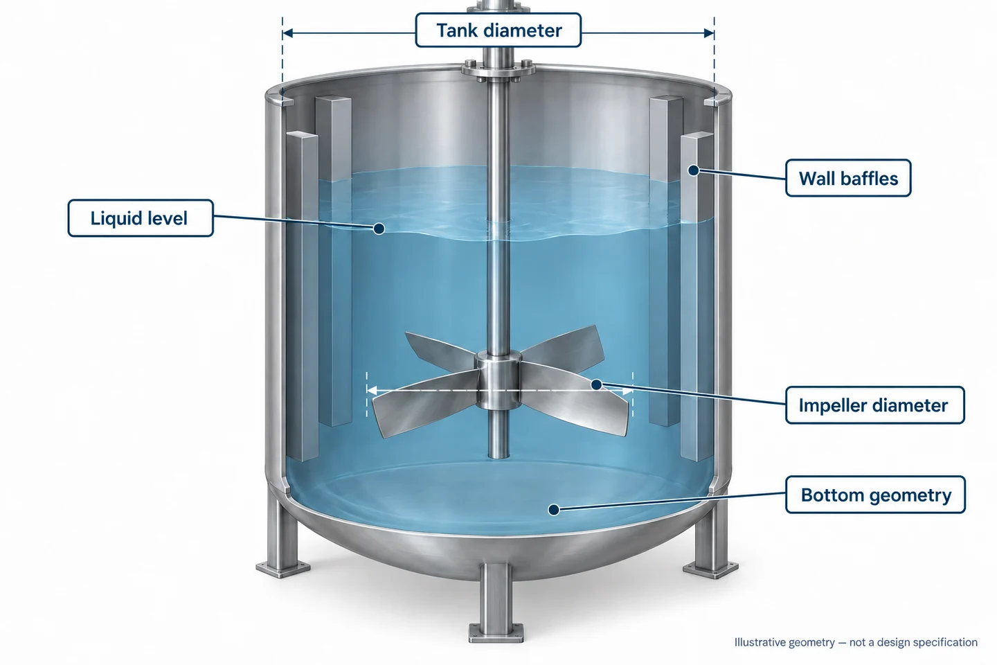
Baffles are not automatically harmful because they introduce stationary surfaces. They also affect bulk circulation and swirling. Removing them to make a tank look gentler changes the system and requires engineering review. Similarly, increasing diameter while reducing speed can change torque, shaft loading and clearance requirements.
The broader mixer impeller design checklist helps collect these installation inputs. For shear-sensitive service, add the product-quality acceptance method to that same arrangement record.
Qualify product integrity and mixing performance together
Define two pass criteria before the trial
One criterion should confirm the required mixing result, such as a specified concentration distribution or an agreed suspension condition. The other should confirm product integrity, using the application-specific test discussed above. Meeting only one does not qualify the arrangement.
Record the starting material condition. Otherwise, incoming particle variation, temperature history or prior processing can look like a mixer effect. Include the time between sampling and analysis where properties change during storage or recovery.
Compare candidates at a useful endpoint
A same-rpm comparison is easy to organize but can be misleading. Two impellers at the same speed might produce very different circulation. Compare quality at the required mixing endpoint while recording speed, diameter, time, temperature, fluid properties, fill level and installed geometry.
Use a sampling plan that represents the batch. One sample beside the impeller does not establish top-to-bottom uniformity. Likewise, a transfer line or sampling valve can change fragile particles before measurement. The trial owner should check whether sample handling itself affects the result.
Investigate the rest of the process before blaming the blade
If quality falls after transfer but remains acceptable in the tank, examine the transfer operation before changing the impeller. If deterioration appears during a long hold, compare the actual hold duration and agitation sequence. These are investigation steps, not instructions to operate outside an approved envelope.
For multi-stage formulations, aggressive mixing can be needed before sensitive ingredients are introduced. Silverson’s bottom-entry mixer explanation distinguishes localized high-shear processing from bulk distribution by a slow-speed stirrer. That distinction supports reviewing each process stage separately; it does not establish a suitable recipe or equipment configuration for your product.
Scale-up requires another review. Constant rpm, tip speed or average power per volume each preserves only part of the original situation. Ask the responsible mixer engineer which criteria are being maintained, which change, and how the production batch will be accepted.
Turn the approved result into manufacturing requirements
A successful trial is useful only if the supplied component reproduces the relevant approved features. “Similar shape” is not sufficient change control for a sensitive mixing duty.
Specify blade profile, width, thickness, pitch, leading/trailing-edge condition, diameter and hub position on the controlled drawing or model. Any rounding, polishing or blending of edges needs an agreed definition. Do not let workshop finishing become an undocumented geometry change.
| Manufacturing control | Requirement to define | Why it matters to repeat orders |
|---|---|---|
| Blade geometry | Approved model/revision, profile, pitch, diameter and edge treatment | Preserves the geometry assessed during qualification |
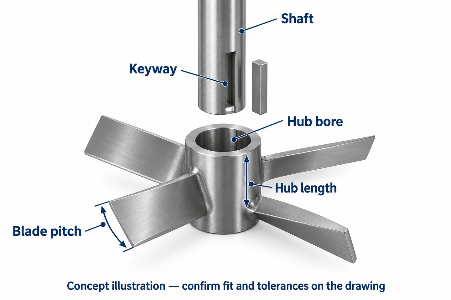
| Mounting interface | Bore, keyway/clamp/flange, hub length, axial location and datum | Maintains fit, orientation and installed position |
| Material and finish | Exact alloy, product-contact surfaces, weld finishing and treatment requirements | Controls compatibility, cleaning and contamination risks without a generic “polished” claim |
| Fabrication or casting route | Approved route, weld details, machining stages and change-approval requirements | Prevents substitutions from silently changing critical features |
| Inspection and release | Drawing-specific dimensions, runout setup, balance requirements and report package | Provides evidence of part conformity, separate from process-performance acceptance |
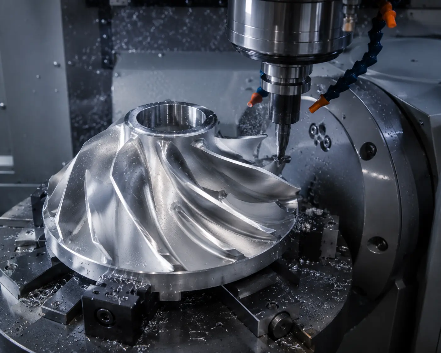
For stainless steel, specify the alloy and any required polishing or passivation rather than using “food grade” as the complete requirement. Surface condition, chemical compatibility and cleanability need their own acceptance basis. A photograph does not prove alloy identity or hygienic compliance.
Dynamic balancing and runout checks address mechanical conformity when specified. Neither certifies low shear. The impeller manufacturing capabilities page explains the component-production scope; process performance remains a separate approval.
What to send with a low-shear impeller RFQ
Send a controlled drawing or 3D file alongside the process context. A useful package includes:
- The property being protected, its test method and the approved mixing endpoint.
- Material description, temperature range, rheology and relevant solids or inclusions.
- Tank dimensions, liquid-level range, baffles/coils and impeller position.
- Approved impeller geometry, rotation viewed from a named side and pumping direction.
- Shaft/hub connection, speed envelope and mechanical loads confirmed by the equipment engineer.
- Exact alloy, surface requirements, inspection plan, quantity and drawing revision.
- Trial reference and an explicit list of changes requiring approval.
If you have only a sample, mark bent, worn, repaired and polished areas before measurement. A worn edge is evidence of its current condition, not necessarily the original qualified profile. Record which dimensions need engineering reconstruction and approval before production.
Separate questions for quotation from questions for qualification. A manufacturer can assess whether a defined metal component is manufacturable and inspectable. That does not mean an incomplete application description is enough to approve its mixing performance.
Avoid these shortcuts when approving a replacement design
“The speed is lower, so the material is safe.” Diameter, local geometry and run duration are missing from that conclusion.
“Its power number is lower, so it creates less damaging shear.” A coefficient for overall power is not a local damage map. Compare the actual duty and quality result.
“The blade is smoother, so it must perform better.” Finishing can help meet specified surface requirements, but uncontrolled rounding changes geometry. Obtain approval for the finished condition.
“The small trial passed, so the production tank needs the same rpm.” Production geometry and exposure differ. Document the scale-up basis and acceptance test.
“No visible fragments means no damage.” Appearance alone might miss a rheological or distribution change. Use the test that reflects the protected property.
How Matson supports suitable custom projects
Matson manufactures custom industrial mixer and agitator impellers from approved drawings, models or suitably reviewed samples. For an RFQ, the team can review material, geometry, machining interfaces, surface-treatment requirements, inspection documents and packing needs against the project specification.
For repeat production, identify the accepted drawing revision and first-article reference. Require approval before a material, process route, blade profile or finishing change affects controlled characteristics. This gives purchasing and inspection a common release basis without asking a part supplier to guarantee an unqualified formulation outcome.
Frequently asked questions
What is the best mixing impeller for shear-sensitive materials?
There is no universal best mixing impeller for shear-sensitive materials. An axial-flow hydrofoil is a candidate for bulk circulation in a sufficiently mobile liquid, while viscous products can require other arrangements. Select against a defined mixing endpoint and a measured product-integrity limit. Confirm the actual geometry, tank configuration and operating conditions before releasing the manufacturing specification.
Can I specify a maximum rpm instead of a product-damage test?
Maximum rpm is a useful operating restriction, but it does not establish acceptable product damage. Diameter determines tip speed, and geometry, clearances and exposure time affect the actual process. Keep the engineer-approved speed envelope on the equipment specification, then verify the protected property using a representative test. Do not ask a component supplier to infer that limit from rpm alone.
Is shear thinning the same as permanent polymer degradation?
No. Shear thinning describes a decrease in apparent viscosity under shear and is not automatically evidence of permanent polymer degradation. Recovery behavior, temperature, measurement conditions and material chemistry matter. Agree on sample conditioning and a suitable test with the process owner or material supplier. Compare results under the same method before attributing an observed viscosity change to irreversible damage.
Should I use a larger impeller at a lower speed?
That combination deserves evaluation, not automatic approval. It changes circulation, tip speed, mechanical loading and vessel clearances together. A larger diameter can also alter torque requirements and the shaft or hub review. Ask the mixer engineer to compare feasible arrangements at the required mixing endpoint, including product integrity. The manufacturer should work from the geometry and loads that receive approval.
Does a polished stainless steel impeller guarantee gentle mixing?
No. Polishing describes surface treatment, not the complete shear environment. Define alloy, surface requirements and permitted edge treatment, then inspect those features against the drawing. Product damage also depends on geometry, speed, clearances, rheology and exposure time. Avoid accepting a shiny sample as process-performance evidence or allowing polishing to change a qualified blade profile without approval from the responsible engineer.
What should I measure during a fragile-particle mixing trial?
Measure the particle attribute that matters, such as size distribution or acceptable fines, alongside the required mixing or suspension result. Record the starting condition, sampling locations, duration, temperature, fill level and impeller arrangement. Check that the sampling equipment does not itself damage particles. The process owner should define acceptance limits and confirm that the trial represents the intended production duty.
Can I copy the existing impeller from a used sample?
A used sample can support measurement, but it might contain worn edges, bent blades or undocumented repairs. Mark those areas and provide service history, photos and any original drawings. Confirm which dimensions represent the qualified design before approving reproduction. Matson can review suitable sample-based manufacturing, while the equipment or process owner approves reconstructed geometry and any consequences for product quality.
What information does Matson need before quoting the impeller?
Send the approved drawing or model, material grade, quantity, shaft connection, speed requirements, surface finish and inspection needs. Include tank arrangement and the relevant process conditions so manufacturing questions can be identified early. For shear-sensitive duty, also state the qualified geometry and change-control requirements. Product-quality qualification remains with the responsible process team rather than being inferred from the quotation.
Final Thoughts
Gentle mixing requires enough circulation to complete the job and controlled exposure to protect the material. An rpm limit or a low-shear label cannot demonstrate both. Define the quality test, qualify the installed arrangement and preserve its approved geometry through manufacturing and repeat orders. Matson can review suitable custom metal impeller requirements once the drawing, material, interfaces and inspection criteria are clear.
Ready to source the approved component? Send Matson your drawing and RFQ requirements, including material, quantity, operating envelope, surface finish and the features that must match the qualified design.