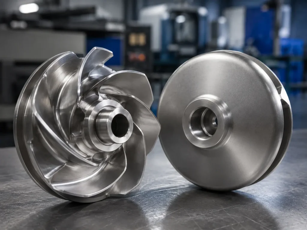
A recessed impeller pump positions the rotating element back from the main casing flow path so more of the passage remains open for solids, fibers, gas-laden liquid or irregular contaminants. This arrangement can reduce blockage risk, but it usually trades hydraulic efficiency for freer passage. Before you specify or reproduce one, confirm the recess depth, casing geometry, duty point, solids profile, material, shaft interface, rotation and inspection requirements as one connected pump assembly.
What is a recessed impeller pump?
A recessed impeller pump is a centrifugal solids-handling pump in which the impeller sits outside, or partly outside, the main flow-through region of the casing. The rotating impeller establishes circulation that transfers energy to the liquid in the larger casing space. Because less of the pumped material must pass through narrow vane channels, the arrangement can suit wastewater, sludge, pulp stock and liquids containing large or long contaminants.
Terminology is not completely uniform. Many pump manufacturers use recessed impeller, vortex impeller, free-flow impeller or torque-flow pump for closely related hydraulic arrangements. KSB describes a torque-flow or vortex-flow pump as using a ribbed free-flow impeller that acts indirectly on the liquid. Xylem’s Flygt handbook groups the terms “recessed / vortex impeller” in its wastewater hydraulic-end discussion.
The terms should still not be substituted blindly on a drawing. Sulzer’s non-clog pump literature notes that a vortex impeller may also be installed farther recessed to obtain a larger passage. That distinction matters: two parts called “vortex impellers” may have different axial positions, casing relationships and performance curves. For manufacturing, the controlled drawing, pump section and approved OEM terminology take priority over a search phrase.
Recessed, channel, open and closed impellers compared
This table is a first selection screen, not permission to change an approved pump design. Hydraulic selection remains with the pump OEM or responsible engineering owner.
| Impeller arrangement | Flow and solids path | Typical strength | Main limitation to review | RFQ evidence needed |
|---|---|---|---|---|
| Recessed / vortex | Impeller is set back from the principal casing passage; much of the liquid and solids move through the casing space. | Large free passage and reduced exposure of solids to narrow vane channels. | Lower hydraulic efficiency and possible accumulation or wear inside the volute. | Pump section, recess depth, casing profile, solids, duty point and approved curve. |
| Channel / non-clog | Liquid and solids travel through one or more defined impeller channels. | Can combine solids passage with stronger hydraulic efficiency. | Fibers or soft solids may catch at leading edges; actual throughlet depends on design. | Channel geometry, throughlet, fiber condition, clearances and clogging history. |
| Open | Exposed vanes act directly on the liquid without a front shroud. | Accessible for inspection and cleaning; useful for selected dirty-liquid duties. | Vane-tip wear and front clearance can affect performance. | Vane profile, casing or wear-plate relationship, axial clearance and wear pattern. |
| Closed | Liquid passes through enclosed vane passages between shrouds. | Often suited to cleaner liquids where controlled passages and efficiency matter. | Narrower passages are less tolerant of difficult solids and hidden wear is harder to inspect. | Eye, outlet width, shrouds, wear-ring surfaces, casing fit and liquid cleanliness. |
How the recessed arrangement creates free passage
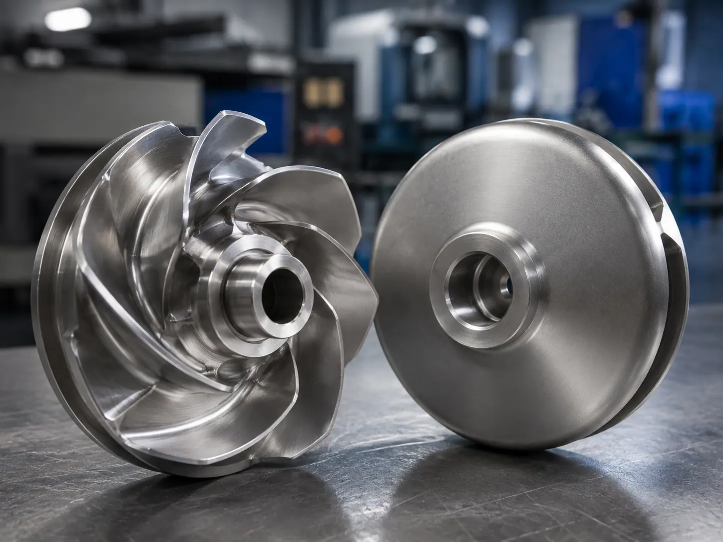
The useful feature is not simply an open-looking impeller. It is the axial relationship between the impeller and casing. When the impeller is set back into a chamber, the main passage through the volute can remain comparatively unobstructed. A rotating liquid mass couples energy from the impeller area into the flow path, while larger contaminants can pass through more of the casing without travelling through a conventional enclosed impeller channel.
This arrangement is why recessed or free-flow hydraulics appear in sewage, sludge, pulp and contaminated-liquid pumps. KSB specifically identifies wastewater and pulp-pump use and relates indirect action to reduced clogging risk and lower sensitivity to gas in the liquid. Sulzer’s non-clog pump literature describes vortex impellers as suitable for large and long solids and states that a more recessed installation can increase the passage.
Free passage is a pump-level property. It is not equal to the impeller outside diameter, eye diameter or the widest visible space between vanes. The limiting path may involve the suction opening, casing, discharge, back chamber or another internal feature. If you need a defined spherical passage or maximum contaminant size, obtain it from the approved pump hydraulic data rather than calculating it from an isolated impeller photograph.
Where a recessed impeller pump fits
The design is worth reviewing when continuity of flow through difficult liquid is more important than reaching the highest possible clean-water efficiency. Suitable discussions may include municipal or industrial wastewater, sludge, effluent, pulp stock, entrained gas and liquid carrying large, long or irregular contaminants.
The application name alone is not enough. “Wastewater” may mean screened effluent with limited solids, raw sewage containing wipes and fibers, abrasive grit, corrosive process discharge or variable sludge. Each condition changes the right geometry, material and operating decision. The water and wastewater impeller page covers Matson’s broader industry scope; this article owns the narrower recessed-position and RFQ issue.
A recessed design can also tolerate gas in selected services better than a tightly channelled arrangement, but it is not a universal answer for aeration, cavitation or poor suction conditions. Gas fraction, suction layout, NPSH margin and duty point remain system engineering questions. Likewise, a large free passage does not prove that stringy material cannot wrap around the hub or that soft solids cannot accumulate in the rotating element or volute.
The efficiency and reliability trade-off
Recessing the impeller reduces direct obstruction in the main flow path, but it also changes how efficiently energy reaches the pumped liquid. Xylem’s Flygt handbook explains that lower hydraulic efficiency requires more shaft power for the same flow and head. Sulzer’s literature likewise states that its channel-impeller versions achieve higher efficiency than its vortex versions, even though the vortex option offers larger-solids capability.
Do not turn that general trade-off into a universal efficiency penalty. Vane geometry, recess, casing design, size, speed and duty point all matter. Compare approved pump curves at the required operating point, including absorbed power, motor margin and expected operating hours. A pump chosen only for maximum free passage may create unnecessary energy cost if the actual liquid is relatively clean.
Reliability is also more nuanced than “vortex means non-clog.” Xylem’s discussion of sustained efficiency reports that traditional non-clog and vortex hydraulics can collect soft solids on impeller or volute features and that partial clogging can reduce flow without stopping the pump. If your process contains wipes, rope-like fibers or rag balls, ask how the complete hydraulic end expels them during continuous and variable-speed operation. A large casing space helps, but no impeller name makes a pump clog-proof.
Casing position is a controlled manufacturing dimension
For a recessed impeller, axial position is a functional feature. The drawing package should define the impeller’s relationship to the casing cover, volute, suction opening and shaft shoulder. Recess depth may be controlled by the hub length, mounting face, shaft step, spacer, sleeve, nut or another assembly feature. Copying only the visible vane envelope can place the new part at the wrong hydraulic position.
If you are sourcing from a worn sample, send the casing section and mating dimensions whenever possible. A rubbed hub face, repaired shaft, replaced spacer or ground vane may have changed the original location. Ask the supplier to separate measured sample dimensions from approved nominal dimensions. Where evidence conflicts, the pump OEM or engineering owner should decide which value controls production.
Rotation direction also requires an explicit viewing convention. State clockwise or counterclockwise as viewed from the suction side, drive side or shaft end, and show an arrow on the drawing. Do not infer rotation from curved vanes alone; a mirrored model or wrong viewing side can produce a part that fits the shaft but cannot perform the intended duty.
RFQ decision table for a recessed impeller
Use the following review before releasing a quotation or purchase order.
| RFQ item | Why it matters | What you should provide | Do not assume |
|---|---|---|---|
| Hydraulic identity | Recessed, vortex, free-flow and torque-flow terminology varies by OEM. | Controlled part name, pump model context, drawing number and revision. | A similar name proves interchangeability. |
| Impeller-to-casing position | Axial setback helps define the passage and flow coupling. | Pump section, recess depth, hub stack, shaft shoulder and mating-part dimensions. | The impeller sample alone preserves original position. |
| Liquid and solids | Large hard particles, soft fibers, grit and gas create different risks. | Solids size, concentration, shape, hardness, fiber length, gas and settling behavior. | “Dirty water” is a production specification. |
| Duty and speed | Flow, head, speed and operating point affect power and approved geometry. | Rated flow, head, speed, rotation, curve reference and operating pattern. | A freer passage guarantees adequate performance. |
| Material | Corrosion, abrasion and impact can occur together. | Exact grade, standard, chemistry, temperature, certificate and heat-treatment requirements. | Stainless steel is always the best wear material. |
| Functional interfaces | Bore, keyway, taper, hub faces and retention features control assembly and runout. | Datums, fits, tolerances, surface finish and mating shaft information. | General dimensions are enough for a rotating part. |
| Inspection and balance | Geometry and mass distribution affect repeatability and vibration. | Inspection plan, report format, runout checks, balance condition and acceptance criteria. | Balancing can correct wrong geometry or fit. |
Material, casting, machining and inspection
Material selection starts with the service, not the impeller label. Abrasive grit may attack vane edges and casing surfaces. Chlorides or process chemicals may cause corrosion. Long contaminants may impact or wrap around features. The exact material grade should be confirmed against the fluid, solids, temperature, expected wear mechanism, approved drawing and documentation requirement.
A recessed impeller may be cast near net shape and then machined at the bore, keyway, taper, hub faces, shaft seat or other critical interfaces. The manufacturing route depends on geometry, alloy, size, quantity and inspection access. Casting allowances must not erase a functional recess, vane transition or back feature. Conversely, a surface that only needs to remain as-cast should not receive an invented machining tolerance.
Inspection should connect the rotor to its assembly function. Useful checks may include outside diameter, vane envelope, hub height, bore and keyway, mounting-face position, axial runout, radial runout and the dimensions that establish casing setback. A coordinate report on the impeller cannot prove the casing recess unless the mating geometry is also defined.
Dynamic balancing may be required according to the drawing, operating speed and approved condition. Record whether the impeller is balanced alone or with sleeves, keys, nuts or other rotating hardware. Balance correction does not repair incorrect recess depth, wrong rotation, unequal vane geometry, excessive runout or a damaged shaft fit.
Matson’s impeller manufacturing capabilities include casting, 3-axis and 5-axis CNC machining, surface treatment, dimensional inspection and dynamic balancing for suitable drawing-based projects. The process and acceptance route are confirmed project by project; no universal tolerance or maximum size is assumed here.
What not to decide from a worn sample
A physical sample is useful for material verification, geometry capture and assembly review, but service damage can hide the original hydraulic definition. Do not copy reduced vane thickness, eroded edges, rubbed faces, corrosion pits, repair welds or a bore that has fretted on the shaft. Mark every questionable surface and provide failure photos before cleaning or repair removes evidence.
The sample also cannot reveal the approved flow, head, power or free-passage requirement. It may show how the impeller was made, but not whether the pump was operating correctly. If a new part is expected to change clogging, efficiency or capacity, that becomes a hydraulic redesign rather than simple reproduction. Matson can review manufacturing feasibility; performance changes need approval from the pump OEM or responsible engineer.
How Matson supports suitable custom projects
Matson manufactures custom metal pump impellers from drawings, 3D models, samples and defined specifications for industrial OEM and repeat-supply projects. For a recessed impeller, the most useful inquiry includes the pump section, axial position, casing interface, material grade, duty data, solids profile, rotation, shaft connection, quantity and required reports.
The commercial product destination for vortex-style custom inquiries remains Matson’s vortex impeller pump page. This article does not offer a complete pump, promise a hydraulic redesign or target household sewage-pump replacement. Its role is to help you define the rotating component and its assembly evidence before quotation.
Common questions about recessed impeller pumps
Is a recessed impeller the same as a vortex impeller?
The terms often describe the same general free-flow hydraulic family, and some OEM literature explicitly groups “recessed / vortex” together. They are not safe substitutes on a production order, however. Recess amount, vane form, casing chamber and terminology vary by manufacturer. Keep the controlled OEM name, provide a pump cross-section and define the axial position rather than asking a supplier to interpret the words alone.
Why does a recessed impeller pump handle solids?
The impeller sits back from much of the main casing passage, leaving a comparatively open route for the pumped liquid and contaminants. Energy is coupled through rotating flow in the casing instead of requiring every solid to travel through narrow enclosed vane channels. Actual solids capacity still depends on the complete suction-to-discharge path, casing, impeller geometry and contaminant shape; it cannot be derived from impeller diameter alone.
Is a recessed impeller pump always non-clogging?
No. Recessed or vortex geometry can reduce blockage risk, especially for large or long contaminants, but fibers and soft solids may still collect on the impeller, hub or volute. Abrasive sediment can also wear internal surfaces. Review actual solids, fiber length, operating cycle, variable-speed behavior and prior clog locations. “Non-clog” is a design objective, not a guarantee that maintenance or screening is unnecessary.
Does recessing the impeller reduce efficiency?
It commonly creates an efficiency trade-off because less energy is transferred through a tightly controlled impeller passage. The size of that trade-off is not universal. Compare the approved pump curves for recessed and alternative hydraulics at your required flow and head, then consider motor power, operating hours and blockage risk. The lowest clean-water energy figure may not deliver the lowest lifecycle cost in contaminated service.
What dimensions matter most for a replacement recessed impeller?
Outside diameter and bore are not enough. Confirm the axial recess relative to the casing, hub height, mounting face, shaft shoulder or spacer stack, vane envelope, rotation, keyway or taper and any back features. Include the pump section and mating-part dimensions. If the sample is worn, separate measured values from approved nominal values so service damage does not become the new production geometry.
Can Matson select a recessed impeller for a new pump design?
Matson can review whether a supplied recessed impeller drawing, model or sample fits its casting, machining, inspection and balancing scope. Final hydraulic selection, performance prediction, motor sizing and pump-system responsibility should remain with the pump OEM or designated engineering owner. For quotation, provide the approved geometry and requirements; if design changes are proposed, document who will calculate, test and approve the revised hydraulic end.
Final thoughts
A recessed impeller pump is a deliberate solids-handling arrangement, not simply an open impeller with a different name. Its value comes from the complete casing passage and controlled axial setback, while its main trade-offs involve efficiency, power and possible solids accumulation. For repeatable custom production, connect the hydraulic drawing to material, shaft fit, inspection and balancing requirements before releasing the part.
Need a recessed or vortex-style impeller manufactured for an industrial OEM project? Send the drawing, pump section, 3D model or marked sample, material grade, solids condition, duty point, rotation, shaft interface, quantity and inspection requirements through Matson’s contact page. We can review manufacturing feasibility and the casting, machining, inspection and balancing route before quotation.