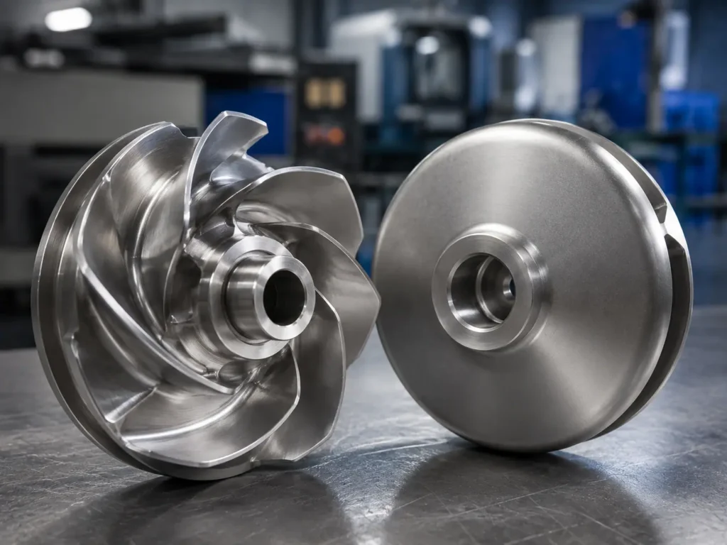
A cross section of impeller geometry shows how the inlet eye, vane passages, front and rear shrouds, hub, bore and outlet relate along the flow path. For an OEM quotation, the section is useful only when its cutting plane, dimensions, datums and rotation convention are clear. A sectional image explains structure; it does not replace an approved drawing, 3D model or pump-duty specification.
What does a cross section of an impeller show?
In a centrifugal pump impeller, liquid normally enters near the shaft axis through the eye, moves between the vanes and leaves at the outer diameter. The Hydraulic Institute’s pump definitions describe radial-flow impellers in the same basic terms: axial entry at the eye, followed by turning through the vanes and shrouds toward a discharge perpendicular to the shaft axis.
A section through the rotation axis can make that path easier to read. It can reveal:
- the eye diameter and inlet contour;
- vane leading-edge position near the eye;
- the internal passage between adjacent vanes;
- front- and rear-shroud profiles;
- outlet width and outside diameter;
- hub height, bore, keyway or other shaft interface;
- wear-ring or casing-clearance surfaces when present;
- changes in wall and vane thickness from inlet to outlet.
The picture is still incomplete unless the drawing identifies what kind of section it is. A meridional or axial section through the shaft centerline shows the inlet-to-outlet profile. A view normal to the shaft is better for vane count and angular spacing. A local vane section may show thickness or profile at one defined radius. Calling all three a “cross section” creates avoidable RFQ errors.
Read the flow path before reading isolated dimensions
The most useful way to read an impeller section is from inlet to outlet, not as a collection of disconnected diameters.
Start at the eye. Note the inlet diameter, edge contour and where the vane leading edges begin. Follow the passage between the vane surfaces and the shrouds. Then check how the passage height and width change toward the outlet. At the discharge, confirm the outside diameter, outlet width, vane trailing-edge position and any specified relationship to the casing or diffuser.
KSB’s centrifugal pump vane reference distinguishes the vane inlet and outlet edges and explains how shrouds or the casing bound the flow passage. That terminology matters in a purchase package. “Vane width” could mean thickness, passage width or axial outlet width unless the feature and measurement location are identified.
The shaft connection must be read at the same time. Bore size, taper, keyway, threads, hub face and axial position determine how the rotating geometry sits in the assembly. An accurate flow passage with the wrong hub datum is still an unusable part.
Impeller cross-section decision table
This table turns the visible features into practical drawing and RFQ checks.
| Section feature | What it tells you | What the drawing should control | Risk if it is unclear |
|---|---|---|---|
| Eye and inlet contour | Where liquid enters and how it approaches the vane leading edges. | Eye diameter, inlet radii or profile, leading-edge location and suction-side interface. | Wrong inlet geometry, reduced passage area or a sample-based copy of worn material. |
| Vane passage | The internal route from inlet to outlet. | Vane count, profile, thickness, spacing, leading/trailing edges and section locations. | A visually similar part with different passage geometry or rotation. |
| Front and rear shrouds | Whether passages are enclosed and how the walls change through the section. | Shroud profile, thickness, machined zones, wear-ring surfaces and allowed repairs. | Distortion, weak sections, incorrect clearance or inaccessible inspection areas. |
| Outlet | Where flow leaves the impeller at the periphery. | Outside diameter, axial outlet width, trailing-edge form and trim status. | Mismatch with the approved hydraulic geometry or casing relationship. |
| Hub and bore | How the impeller mounts and where functional datums may be established. | Bore or taper, keyway, hub faces, axial position, fit and geometric controls. | Poor shaft fit, incorrect assembly position, runout or balance problems. |
| Clearance interface | Where the impeller approaches a wear ring, casing, liner or side plate. | Feature diameter, face position, datum, finish and mating-part information. | Rubbing, excessive leakage or an RFQ based on only one worn component. |
A sectional view is not the same as a complete manufacturing definition
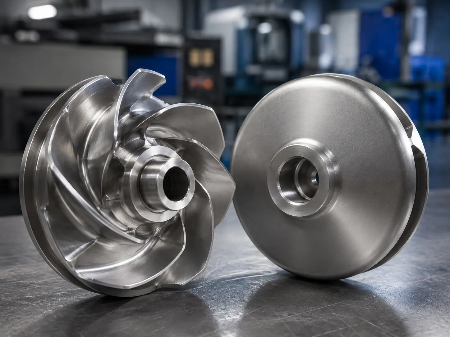
One section can hide important geometry. A centerline section usually cannot define the full three-dimensional vane sweep, angular spacing, splitter vanes or local profile changes around the circumference. A photograph of a cut part can show internal construction, but perspective and wear make it unreliable for measurement.
Use the right information source for the decision:
| Information source | Useful for | Main limitation | Recommended RFQ use |
|---|---|---|---|
| 2D sectional drawing | Axial profile, named dimensions, datums, fits and notes. | May not fully define twisted or free-form vane geometry. | Use as a controlled dimension and specification source. |
| 3D model | Complete vane surfaces, internal passages and manufacturing review. | May omit tolerances, material, finish and inspection requirements. | Send with a controlled 2D drawing or specification hierarchy. |
| Physical sectioned sample | Internal construction, thickness and damage observation. | Destructive, possibly worn, repaired or distorted. | Use as supporting evidence, not automatically as nominal geometry. |
| External photographs | Part identification, visible structure and damaged-area marking. | Cannot reliably define hidden passages, scale or true profiles. | Use to start review and show condition, not to release production. |
| Complete undamaged sample | Assembly features and direct dimensional investigation. | Service wear may have changed clearances, edges and balance. | Identify wear history and approve reconstructed nominal dimensions. |
If your 3D model and 2D section disagree, state which source controls. Do not let the supplier choose silently. A useful hierarchy might identify the model as the geometry master while the drawing controls tolerances, material, finish and inspection, but the correct hierarchy must come from the project owner.
Dimensions and datums that connect the section to the assembly
The section becomes commercially useful when its geometry is tied to functional references. For many pump impellers, the bore axis is an important datum candidate, while a hub or mounting face controls axial location. The actual datum scheme must follow the approved design; it should not be copied from another impeller simply because the parts look similar.
Common section-related controls include:
- outside diameter and whether it is nominal, finished or trimmed;
- eye diameter and inlet profile;
- outlet width measured at a stated location;
- bore, taper, keyway and hub-face relationship;
- shroud thickness at identified sections;
- vane thickness and passage width at defined stations;
- wear-ring seat or other casing-interface diameters;
- axial distance between mounting and hydraulic features;
- radial or face runout tied to stated datums;
- surface condition for machined, polished, coated or as-cast zones.
Avoid dimensions taken from an unscaled PDF screenshot. Also avoid measuring only the accessible edge of a badly worn sample. If an outlet has been trimmed, a leading edge has cavitation loss or a wear-ring surface has rubbed, the current section no longer represents the original nominal form.
For detailed component explanations, use the existing guides to the impeller eye and impeller vanes. This article owns the map of how those features connect; the linked articles retain their individual manufacturing and inspection detail.
How open, semi-open and closed sections differ
An open impeller exposes its vanes toward a mating casing wall or side plate. A semi-open impeller usually has a shroud on one side. A closed or enclosed impeller has front and rear shrouds around the vane passages. Those simple labels help orientation, but they do not define a production-ready part.
In an open design, the cross section should make the open-side clearance relationship understandable. That means the mating casing, liner or wear plate may be essential RFQ information. In a closed impeller, the internal passage is harder to see and inspect, so the 3D model, core or casting route, internal surface requirement and inspection approach deserve more attention. Semi-open forms sit between those cases and still need an unambiguous statement of which side is open.
Single-suction and double-suction arrangements also change the section. A double-suction impeller has inlet flow from both sides and introduces symmetry, dual inlet and wear-surface questions. Do not infer the second side from one incomplete drawing view.
Manufacturing and inspection implications
The impeller section influences process planning because internal geometry controls whether the part is cast, machined from stock, fabricated, or produced through a combined route. It also shows where tools, gauges and visual inspection may or may not have access.
For a cast-and-machined impeller, the review should separate as-cast surfaces from finished features. Casting allowance around the bore, hub, eye, outlet or wear surfaces must support a stable machining setup without erasing required wall thickness. Closed passages add core, cleaning and internal-inspection questions. Local grinding or blending can alter passage geometry and rotating mass even when the outside dimensions still pass.
For a fabricated impeller, the section can define plate thickness, hub joints, vane-to-shroud fit and weld locations. Welding sequence, distortion control and post-weld inspection then become part of the manufacturing plan. For a CNC-machined impeller, tool access, setup datums, residual material, edge condition and measurement strategy need review against the complete 3D form.
Matson’s impeller manufacturing capabilities cover investment casting, sand casting, 3-axis and 5-axis CNC machining, surface treatment, dynamic balancing and dimensional inspection. The route is selected against the supplied geometry, material, quantity and acceptance requirements rather than from the sectional picture alone.
Where a cross section helps—and where it does not
A clear section is especially helpful when reviewing a shrouded centrifugal pump impeller, a sample-based remake, a casting with hidden passages or an assembly with critical wear-ring and hub relationships. It can also help a procurement team compare supplier questions: a serious review should address datums, hidden geometry, manufacturing state and inspection access instead of quoting from outside diameter alone.
The section does not establish pump performance by itself. Flow, head, speed, liquid properties, solids, suction condition, casing or diffuser geometry and operating point remain relevant. It also does not authorize a material substitution, change in vane count, new outlet angle or different clearance. Those decisions remain with the pump OEM or responsible engineering owner.
This limitation is important for reverse engineering. A section cut from a worn part can reveal what is present now, not necessarily what the original designer intended. Combine it with undamaged repeated features, mating-component data, earlier drawings, approved samples and service history before releasing new nominal geometry.
What buyers should confirm before an RFQ
If you want the section to reduce quotation uncertainty, label it like controlled engineering information. Your RFQ package should include:
- part number, drawing number and revision;
- section line, viewing direction and scale;
- approved 2D drawing and 3D model where available;
- precedence rule if drawing and model conflict;
- impeller type, suction arrangement and rotation direction with viewing side;
- OD, eye, outlet, bore, keyway, hub and interface dimensions;
- vane count, splitter vanes and local section stations;
- material grade and required certificate;
- machined, as-cast, welded, polished, coated and protected surfaces;
- liquid or gas, temperature, solids, corrosion and abrasion information;
- operating speed and required balance condition;
- dimensional report, NDT or other inspection requirements;
- quantity, first-article needs and repeat-order volume;
- photos and marked wear or repair zones when a sample is supplied.
A manufacturer should not have to guess whether a heavy line is a section boundary, a hidden edge or a wear scar copied from a photograph. Put critical geometry and acceptance requirements in controlled documents, not only in an email thread.
How Matson supports drawing- and sample-based impeller projects
Matson manufactures custom pump impellers for suitable industrial OEM projects from drawings, 3D files, physical samples and defined specifications. Before quotation, the review can cover material, casting or machining route, functional interfaces, inspection access, surface requirement, balancing and documentation.
Matson does not treat one sectional image as permission to redesign the hydraulic passage. If information is missing, the useful next step is to identify the open decisions: which geometry controls, which dimensions are nominal, what has worn, what mates with the impeller and what the supplied part must demonstrate before approval. That approach is slower than guessing at the quote stage and faster than correcting an unusable first article.
Common questions about an impeller cross section
What is the cross section of an impeller?
An impeller cross section is a cut or drawing view used to reveal geometry that an external view cannot show clearly. A section through the shaft axis can show the eye, shrouds, hub, bore, passage height and outlet width. It normally does not define the complete three-dimensional vane sweep, so production still needs the applicable drawing, model, datums, material and acceptance requirements.
Which direction should an impeller section be taken?
The direction depends on the question. A centerline or meridional section is useful for inlet-to-outlet profile, shrouds, hub and bore. A view normal to the shaft helps show vane count and angular layout. Local sections can define vane thickness or passage shape at stated radii. Put the section line and viewing arrows on the drawing so the supplier does not infer the cutting plane.
Can a cross-sectional photo be used to manufacture an impeller?
A photo can support identification and reveal internal construction, but it is rarely sufficient for production. Perspective, unknown scale, wear, cut damage and hidden three-dimensional surfaces limit measurement. Use a controlled drawing or 3D model where possible. If a sectioned sample is the only source, document the cutting plane, compare undamaged repeated features and obtain approval for reconstructed nominal geometry before manufacturing.
What dimensions are most important in a pump impeller section?
Important dimensions commonly include the eye, outside diameter, outlet width, bore, hub height, mounting face, shroud profile, vane thickness and wear-ring or casing interfaces. Their relationships and datums matter as much as the individual numbers. The correct list depends on the pump design. Do not use a generic dimension set as a substitute for the approved assembly and hydraulic requirements.
Does a closed impeller need a more detailed sectional drawing?
A closed impeller often benefits from stronger sectional and 3D definition because the front and rear shrouds hide the vane passages. The manufacturing review may need internal passage geometry, core or casting considerations, wall thickness, machining allowance, cleanout and inspection access. Detail level should match risk and complexity; the answer is not simply to add more dimensions without a clear datum and model hierarchy.
Can Matson reproduce an impeller from a worn sample and one section drawing?
Matson can review a drawing-and-sample project, but a worn sample should not automatically define nominal geometry. Mark cavitation, corrosion, rubbing, trimming, repair welding and missing material. Provide mating-part dimensions, speed, application conditions and earlier records where available. The quotation review should identify which features are reliable, which require reconstruction and who approves the final manufacturing definition before production.
Final Thoughts
A useful impeller cross section connects the flow path to the mounting and clearance interfaces. It names the cutting plane, ties dimensions to functional datums and works with the full drawing or 3D model. When a part must be cast, machined, inspected and balanced for OEM use, resolving those relationships before quotation is more valuable than adding unsupported dimensions after the first article is made.
Send Matson your impeller drawing, 3D model or marked sample information for a manufacturing and RFQ review. Include the section view, material, quantity, operating condition, critical interfaces, inspection and balancing requirements.