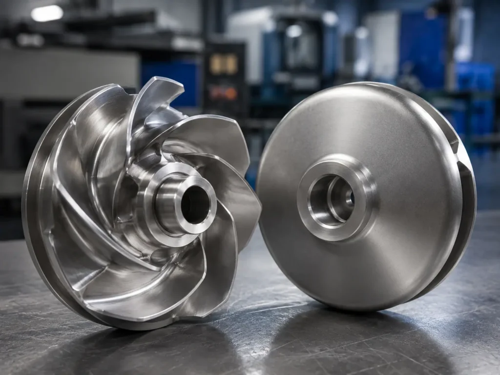
Impeller hardness testing requirements should define the material condition, test method and scale, acceptance range, test location, surface preparation, number of readings, sampling frequency and report format. If your purchase order only says “check hardness,” the supplier may produce a valid number that does not answer your acceptance question. Agree the complete test instruction before casting, heat treatment, finish machining or shipment.
What does an impeller hardness test actually confirm?
A hardness test measures a material’s resistance to indentation under a defined method. For an industrial impeller, the result may support verification of an agreed heat-treated condition, wear-resistant alloy condition or batch-consistency requirement. It can also reveal an unexpected difference between parts, locations or production lots that needs investigation.
Hardness is not a complete material certificate. It does not by itself prove alloy chemistry, toughness, corrosion resistance, casting soundness or hydraulic performance. Two materials can return similar hardness readings while differing in composition and service behavior. Use the separate impeller material verification process when the purchase decision depends on confirming grade and traceability.
The acceptance basis should come from the applicable drawing, material specification, heat-treatment specification or buyer-approved project requirement. Matson should not invent a hardness range after testing, and a buyer should not copy a value from an unrelated alloy or impeller.
Specify the method and scale, not just a number
“Hardness 220” is incomplete because the number depends on the test method and scale. Brinell, Rockwell and Vickers tests use different indenters, forces and result designations. Portable methods may be useful for some large parts or locations, but their suitability and correlation need agreement for the actual material, geometry and acceptance decision.
ISO 6506-1 covers the Brinell method for metallic materials and includes fixed-location and portable testing machines. ISO 6507-1:2023 specifies Vickers testing across defined test-force ranges. ISO 6508-1:2023 covers regular and superficial Rockwell scales for stationary and portable machines. These standards define test methods; they do not select the correct hardness limit for every impeller.
Your RFQ should identify the governing standard edition, complete scale designation and acceptance limits. If the material or product specification already defines the method, use that requirement consistently unless an authorized deviation is agreed.
Impeller hardness test decision table
Use this table when deciding what needs to be resolved before the test instruction is released.
| Project condition | Useful test direction | Main limitation | What the buyer should confirm |
|---|---|---|---|
| Cast impeller requiring a bulk-condition check | Brinell may be considered where the material specification, section and test surface suit it. | The indentation is relatively large, and curved, thin or inaccessible areas may not provide a valid location. | Test surface, section thickness, location, number of readings and permitted witness area. |
| Machined steel or alloy feature with an agreed scale | Rockwell may offer a direct production check on a suitable supported surface. | Wrong scale, poor support, curvature or surface condition can make the result unsuitable. | Exact Rockwell scale, finish, support, edge distance and final manufacturing stage. |
| Small local zone, thin section or detailed comparison | Vickers may be considered when the selected force and prepared surface match the purpose. | Surface preparation and optical measurement become increasingly important at lower forces. | Test force, location map, preparation, indentation acceptance and reporting detail. |
| Large impeller that cannot be placed on a stationary tester | A qualified portable method may be reviewed. | Geometry, mass, surface, orientation and method correlation can affect the decision. | Portable method, procedure, reference blocks, correlation basis and whether direct acceptance is permitted. |
| Drawing uses one scale but supplier proposes another | Test the specified scale whenever practical. | Converted values are estimates and are material- and condition-dependent. | Whether conversion is authorized, which table applies and how the original result will be reported. |
Put the test location on the drawing or location map
Impeller geometry makes location selection a manufacturing issue, not a paperwork detail. A hub, shroud, thick casting section, thin vane and weld heat-affected zone may not represent the same local condition. A test position must also provide enough material support and distance from edges or previous indentations for the selected method.
Do not tell the inspector to test “any accessible area.” Mark the location on the controlled drawing, inspection plan or photograph. Identify whether the reading is taken on the finished component, a designated sacrificial pad, an attached coupon or a separately produced test coupon. If a coupon is used, the governing specification and manufacturing route must establish how it represents the actual impeller or heat.
For a multi-piece fabricated impeller, clarify whether the requirement applies to the hub, blades, backplate, weld area or each material lot. For a casting, decide whether one location can represent the part and whether section variation matters to the engineering decision. If the test mark is not allowed on a functional surface, define an approved witness area before machining removes it.
Control surface condition, support and test stage
Scale, oxide, coating, decarburized material, rough casting texture, machining marks and curvature can affect whether a location is suitable. The test plan should state the required local preparation and the maximum material removal allowed. Grinding deeply until a stable result appears can remove the condition you intended to evaluate or damage a functional surface.
The part must be adequately supported for the selected method. A thin vane that flexes, a curved hub surface or a part that moves during loading can produce a misleading result. Where direct testing is impractical, engineering and quality personnel should agree an alternative location, coupon or method before the supplier reports compliance.
Manufacturing sequence also matters. A reading taken before final heat treatment does not establish the final condition. A reading taken on scale before machining may not represent the finished surface. A coating can make base-metal indentation unsuitable. State whether hardness is checked after casting, heat treatment, stress relief, repair welding, rough machining or final machining, and whether later operations require retesting.
The impeller heat treatment requirements article explains how final material condition and thermal sequence should be controlled. This article covers the evidence needed when hardness is one of the acceptance checks.
Define readings and sampling before production
One reading, an average of several readings and a minimum-to-maximum range answer different questions. The instruction should state how many valid indentations are required at each location, whether individual values or an average control acceptance, and what happens to an invalid or visibly disturbed indentation.
Sampling must be tied to a defined lot. “One per batch” has little meaning unless the batch basis is clear: one heat, one melt, one heat-treatment load, one part number or one production run. If traceability is lost between the tested component and shipped parts, the result cannot support the lot release as intended.
First articles may need a broader location study to prove that the proposed method works on the real geometry. Repeat orders can then use the approved plan, subject to the purchase requirement and change control. Do not reduce the sampling frequency merely because previous results passed. Material-source changes, heat-treatment changes, repair, rework or an abnormal result may trigger additional testing or reapproval.
Avoid casual conversion between hardness scales
Hardness conversion is not an exact replacement for testing the specified scale. ASTM E140 explains that conversions depend on material, microstructure and heat treatment, and that different hardness tests do not measure exactly the same combination of properties. Its conversion values are estimates for the materials and conditions covered.
If your drawing requires HRC, a converted HRC result from another method should not silently replace the direct test. First confirm that direct testing is impractical, the applicable conversion table covers the material and condition, and the buyer authorizes the conversion. The report should retain the original measured value, method and scale, then identify the conversion source and converted value separately.
This becomes especially important near an acceptance limit. Repeatedly converting a number between scales can create false precision. If the decision is critical, arrange an agreed direct test or escalate the issue to the responsible materials and quality functions.
What a hardness test report should contain
A report should make the result traceable and reviewable. At minimum, ask for:
- supplier name and report identifier;
- purchase order, part number and drawing revision;
- impeller serial, lot, heat or batch identity as required;
- material grade and declared heat-treated condition;
- test standard, edition, method, scale and test force where applicable;
- drawing reference, photograph or map for every test location;
- surface preparation and manufacturing stage;
- each original reading, units or designation, and stated acceptance limits;
- equipment identification and verification or calibration status required by the quality plan;
- sampling basis, tested quantity, date, operator and reviewer;
- conversion source, if an authorized conversion was used;
- pass/fail disposition and any nonconformance reference.
A report that says only “hardness passed” does not show what was tested or how. A certificate can be genuine yet insufficient for the purchase requirement. Align the report fields with the drawing and inspection plan before production so the supplier does not have to reconstruct evidence after shipment.
How to handle an unexpected hardness result
First protect the evidence. Identify and segregate the affected part or lot, preserve the original reading and confirm the requirement, scale, test location and units. Then check surface preparation, support, equipment status, reference-block checks, indentation condition and data transcription. Retesting should follow an approved procedure; it should not become repeated testing until a passing number appears.
If a confirmed result is outside the agreed range, investigate material identity, heat-treatment records, lot linkage and any local process such as repair welding or excessive surface removal. The result may indicate a process or traceability problem, but hardness alone does not diagnose the cause.
Rework, additional heat treatment, use-as-is concession or rejection must follow the authorized nonconformance process. After rework, define what needs retesting and whether dimensions, runout, surface condition or dynamic balance could also be affected. The supplier should not change a report to “pass” without preserving the original result and approved disposition.
What to include in an impeller RFQ
Before asking for a quotation, send the controlled drawing and the applicable material and heat-treatment specification. Add the hardness range, method, scale, location map, manufacturing stage, readings per location, lot definition, sampling frequency and report requirement. Identify whether portable testing, test coupons or conversions are allowed.
Also tell the supplier which surfaces cannot be marked, whether the buyer will witness testing, when the report is due and who can approve deviations. For sample-based work, do not assume the old impeller’s hardness is the original design requirement. Service exposure, wear, repair and unknown material history can make a sample reading useful for investigation but unsafe as the sole production acceptance basis.
Matson’s custom impeller manufacturing process can be reviewed against project-specific casting, machining, heat-treatment, inspection and documentation needs. For a new custom industrial impeller, the exact hardness test arrangement must be confirmed for the selected alloy, geometry and order rather than assumed from a general capability statement.
Common questions about impeller hardness testing
Is hardness testing enough to verify an impeller material grade?
No. A hardness result may support a specified material condition or reveal inconsistency, but it does not uniquely identify alloy chemistry or prove toughness and corrosion resistance. Review the material certificate, heat or batch traceability and any required chemical or mechanical tests separately. Use hardness as one controlled piece of evidence, then connect it to the same physical part or production lot.
Which hardness scale is best for an impeller?
There is no universal best scale. Selection depends on the governing material specification, expected hardness range, section thickness, surface condition, curvature, available support, test location and required accuracy. Brinell, Rockwell and Vickers methods each have valid uses and limits. Specify the method and full scale before production; do not let accessibility alone determine the acceptance test.
Can a portable hardness tester be used on a large impeller?
It may be suitable when the applicable standard, material, geometry, surface and project procedure allow it. Confirm the portable method, instrument verification, reference checks, orientation or support limitations and correlation to the required acceptance basis. A convenient portable reading is not automatically equivalent to a stationary Brinell, Rockwell or Vickers result, especially close to specification limits.
Can the supplier convert Brinell hardness to Rockwell hardness?
Only when the buyer’s requirement permits conversion and the selected conversion reference applies to the material and condition. Conversions are approximate, not exact measurements of the requested scale. The report should show the original method, scale and result, the conversion table or equation used and the converted value. Direct testing on the specified scale is preferable when it is practical and valid.
Where should hardness be tested on a cast impeller?
Use a location approved for the specific casting, material and test method. It should represent the condition being accepted, provide suitable thickness and support, avoid invalid edge or curvature effects and not damage a critical interface. Mark the location on a controlled drawing or map. If a coupon or sacrificial pad is used, define how it represents the production impeller.
What should happen after an out-of-range hardness result?
Segregate the affected identity, preserve the original result and verify the requirement, method, surface, location, equipment checks and transcription. If the result is confirmed, investigate material and heat-treatment traceability through the approved nonconformance process. Any rework, retest, concession or rejection needs authorized disposition. Do not retest repeatedly or discard failed readings until a passing value appears.
Final Thoughts
Reliable impeller hardness testing begins with a complete acceptance instruction, not with a tester pressed against the easiest surface. Define the material condition, method, scale, location, preparation, readings, lot and report before production. Matson can review these controls with your custom impeller drawing so the quotation, process route and inspection evidence support the same OEM release decision.
Send Matson your impeller drawing and hardness testing requirements for a project-specific manufacturing and inspection review.