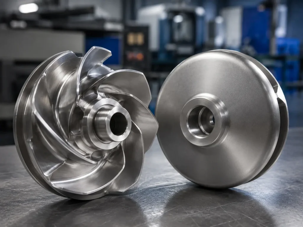
Impeller dimensional inspection is the documented verification that a manufactured impeller matches the approved drawing, model, datum system, and tolerance requirements. It should cover the features that control assembly, clearance, rotation, hydraulic or aerodynamic geometry, and repeat production—not just outside diameter and bore size.
A useful inspection plan states what will be measured, from which datum, at which production stage, with which method, and how the result will be reported. The buyer and manufacturer should agree on critical characteristics, sampling, first-article scope, and acceptance rules before production begins.
Matson can review dimensional inspection requirements for suitable custom pump, fan, blower, mixer, agitator, compressor, and industrial impeller projects made from drawings or samples. Final tolerances and functional acceptance remain controlled by the approved equipment drawing and buyer specification.
[Image placeholder: Add a real factory inspection image showing a custom impeller on a granite table with a controlled drawing, bore gauge, height gauge, caliper, dial indicator, and marked inspection points. Alt text: “Impeller dimensional inspection with drawing gauges and marked features”]
What Impeller Dimensional Inspection Should Prove
Dimensional inspection answers a practical question: does the finished impeller have the correct size, shape, location, orientation, and relationship between features to fit and rotate in the intended equipment?
The result is meaningful only when it is tied to a controlled requirement. A report containing numbers without drawing revision, feature identification, datum, tolerance, or acceptance status is difficult to use. The inspection record should allow the buyer to trace each critical result back to the approved part definition.
The pump impeller dimensions guide explains which OD, eye, bore, hub, shroud, vane, wear-ring, width, and clearance dimensions buyers should define before quotation.
Start With the Controlled Drawing and Revision
Inspection should not begin from an email screenshot, an unapproved sketch, or an old sample alone. The manufacturer needs a controlled 2D drawing, revision, units, general tolerances, material, finish notes, and 3D model where relevant.
For complex impellers, the 2D drawing and 3D model should have a clear order of precedence. If the drawing gives a bore and hub tolerance but the model shows a different nominal size, the discrepancy needs written disposition before machining.
A ballooned drawing is useful for first articles and detailed reports. Each specified dimension or note receives an identification number, and the inspection record uses the same number. This makes omissions easier to find and helps repeat-order teams compare later batches against the approved baseline.
Datum Selection Controls the Result
A datum establishes the reference from which another feature is measured. On an impeller, the functional datum may be the finished bore, taper, pilot, mounting face, shaft centers, flange, or another drawing-defined feature.
Poor datum definition creates disputes. A vane tip measured from an as-cast hub can produce a different result from the same tip measured from the finished bore axis. Both readings may be physically correct, but only one may represent the installed condition.
The inspection setup should reproduce the functional mounting condition as closely as the drawing requires. Fixtures, arbors, centers, plates, and supports must not distort the part or introduce an error large enough to hide the actual condition.
Match Each Feature to a Suitable Method
One measuring tool cannot verify every impeller feature. The method should fit the geometry, tolerance, access, surface condition, and reporting requirement.
| Feature or characteristic | Possible inspection approach | Important limitation or setup point |
|---|---|---|
| Bore, pilot, or finished diameter | Bore gauge, micrometer, calibrated plug, CMM, or agreed dedicated gauge | Confirm measurement depth, temperature, taper, roundness need, coating condition, and whether a worn sample supplied the nominal size |
| Hub height, overall width, and axial position | Height gauge, micrometer, depth gauge, CMM, or fixture-based comparison | Define the datum face, contact locations, interruptions, and whether casting texture affects seating |
| Outside diameter and wear-ring diameter | Outside micrometer, diameter tape where suitable, CMM, rotating setup, or dedicated gauge | Size alone does not prove roundness, concentricity, or runout |
| Face or radial runout | Dial indicator on a controlled arbor, shaft, centers, or drawing-defined fixture | Datum, mounting condition, indicator track, rotation angle, and reporting convention must be stated |
| Keyway, spline, thread, and bolt pattern | Caliper, micrometer, pins, thread gauge, optical method, CMM, or functional gauge | Width alone is insufficient if depth, location, orientation, pitch, or fit controls torque transfer |
| Vane count, angle, thickness, spacing, and profile | Templates, section gauges, angle tools, CMM, optical scanning, or model comparison | Access, reference section, casting texture, edge definition, point density, and approved model alignment affect the result |
| Surface finish | Profilometer, visual comparator, approved sample, coating gauge, or specified test method | Surface roughness, visual appearance, polishing, cleanliness, and coating acceptance are different requirements |
The tool name alone does not prove an inspection is valid. The measurement range, resolution, calibration status, operator method, fixture, environmental condition, and repeatability must be suitable for the specified tolerance.
Size, Form, Orientation, and Location Are Different
A finished bore can meet its diameter tolerance while being out of round. An outside diameter can have the correct average size but be eccentric to the bore. A mounting face can be flat yet not square to the intended rotation axis.
Drawings therefore need to distinguish:
- Size: diameter, width, height, thickness, length, or angle
- Form: flatness, straightness, circularity, cylindricity, or profile
- Orientation: perpendicularity, parallelism, or angular relationship
- Location: position, coaxial relationship, or feature spacing
- Runout: indicator variation of a surface around a defined datum axis
Do not replace these controls with the vague note “all dimensions must be concentric.” The equipment owner should identify the functional relationship and an inspection method that can verify it.
Matson’s impeller runout tolerance article explains radial and face runout, datum setup, mounting condition, reporting, and why runout is not the same as dynamic balance.
Complex Vane Geometry Needs Defined Sections
Curved, twisted, shrouded, hydrofoil, mixed-flow, compressor-type, and other three-dimensional blades cannot be fully controlled with one blade angle or thickness value. The inspection plan may need model-based profile checks at defined sections.
The drawing or inspection plan should identify:
- Blade numbering and viewing direction
- Leading and trailing edges
- Pressure and suction sides where applicable
- Root, mid-span, and tip sections
- Profile tolerance and alignment method
- Blade thickness locations
- Pitch, stagger, or installation angle reference
- Vane spacing and passage width
- Permitted edge blend and casting cleanup
Scanning more points does not automatically make the result more correct. Alignment strategy, datum quality, surface noise, inaccessible passages, probe or scanner limitations, and model revision all affect the comparison. A color map is useful only when the tolerance, alignment, excluded areas, and acceptance logic are agreed.
Inspect As-Cast and Finished Conditions Separately
An impeller may pass through casting, heat treatment, rough machining, welding, stress relief, finish machining, polishing, coating, and balancing. Each step can change dimensions or reveal a hidden problem.
As-cast inspection can verify that the blank has enough machining stock, complete vane geometry, acceptable wall thickness, and no obvious distortion that prevents further processing. Finished inspection should verify the final functional dimensions after operations capable of changing them.
An as-cast surface should not be judged as if it were a machined diameter. Conversely, a feature marked for finish machining should not be accepted only because the casting is close to nominal. The process plan should state which dimensions apply at each stage.
Matson’s impeller manufacturing capabilities cover suitable casting, CNC machining, surface treatment, dimensional inspection, dynamic balancing, documentation, and export packing projects.
Worn Samples Need Reconstruction Decisions
A physical sample is valuable, but wear and repair can hide the original geometry. Common problems include:
- Enlarged, oval, sleeved, or fretted bore
- Worn wear-ring or seal diameter
- Ground vane tips and reduced outside diameter
- Rubbed shroud faces
- Corroded or eroded passages
- Bent fan or mixer blades
- Previous weld repair or added balance weights
- Missing key, nut, sleeve, or mating shaft information
The manufacturer should record which sample features are reliable, which are damaged, and which need an approved reconstruction decision. Copying every measured value from a worn part can reproduce the failure condition rather than the original design.
Whenever possible, combine the sample with an equipment drawing, mating shaft or casing dimensions, old inspection report, unused reference part, assembly photo, or buyer-approved nominal values.
Measurement Capability Must Fit the Tolerance
A tight tolerance is not useful if the selected gauge and setup cannot distinguish acceptable from unacceptable parts. Measurement uncertainty, resolution, repeatability, fixture error, temperature, surface texture, and operator technique all consume part of the available tolerance.
The buyer should avoid assigning very tight tolerances to every dimension. That can increase machining, fixturing, inspection, scrap, and reporting cost without improving function. Critical characteristics deserve capable measurement; non-critical casting envelope dimensions may need a different control level.
If a supplier proposes an alternative method, the comparison should address correlation to the drawing requirement. For example, a functional gauge can be efficient for repeat production, while the first article may still need recorded variable measurements.
Define the Inspection Stage and Sampling Plan
Not every dimension needs to be measured on every part, but critical fit, safety, balance-related, and process-sensitive features may require tighter sampling. The buyer should state whether the project needs:
- Complete first-article dimensional inspection
- 100% inspection of selected critical characteristics
- Batch sampling for stable repeat features
- In-process checks before an irreversible operation
- Final inspection after coating, polishing, or repair
- Reinspection after a drawing, tooling, material, supplier, or process change
First-article approval does not automatically validate every future batch. It establishes a controlled baseline. Repeat production still needs drawing revision control, process discipline, agreed sampling, nonconformance handling, and traceable records.
The custom impeller first article inspection checklist covers material, dimensions, runout, balancing, deviations, approval status, and reapproval triggers for OEM projects.
What a Dimensional Inspection Report Should Include
A practical report should contain:
- Buyer and supplier part number
- Drawing number, revision, model revision, and units
- Part, serial, heat, or batch identification as required
- Balloon or feature number
- Nominal dimension and tolerance
- Actual measured result
- Datum and measurement method where relevant
- Instrument or fixture identification when specified
- Inspection stage and surface condition
- Acceptance status and deviation reference
- Inspector, date, and approval fields
For profile scans, runout setups, or hard-to-identify features, include a marked drawing, setup photograph, section map, or agreed color report. The purpose is not to create paperwork for its own sake. The report should let the buyer understand what was checked and whether it matches the controlled requirement.
Impeller Dimensional Inspection RFQ Checklist
Send the following before quotation:
- Controlled 2D drawing and 3D model with revision
- Units, general tolerances, and governing drawing standards
- Datum system and functional mounting condition
- Critical, major, and non-critical characteristics
- Bore, hub, keyway, mounting face, OD, width, wear-ring, and clearance dimensions
- Vane sections, profile tolerance, thickness, angle, and spacing requirements
- Runout, form, orientation, and location controls
- As-cast versus finished dimensions
- Coating, polishing, passivation, and masking effects on final dimensions
- Inspection methods or approved alternatives
- First-article, 100%, and batch-sampling requirements
- Required report format, ballooning, photos, and traceability
- Mating shaft, casing, sleeve, nut, key, or fixture information
- Sample wear, repair, corrosion, and reliability notes
- Quantity, repeat-order plan, deviation process, and change-control rules
This information lets the supplier assess machining sequence, datum transfer, fixture needs, inspection access, gauge capability, reporting workload, and production cost before committing to the project.
Common Questions Buyers Ask
What is impeller dimensional inspection?
It is the documented verification that an impeller matches the approved drawing, model, datum, dimensions, tolerances, and feature relationships required for fit and function.
Which impeller dimensions are most important?
Critical dimensions commonly include the bore or taper, hub height, mounting face, keyway, outside diameter, overall width, wear-ring surfaces, clearances, vane geometry, and their relationship to the rotation axis. The equipment drawing should decide the final list.
Is a CMM required for every impeller?
No. The suitable method depends on geometry, tolerance, access, surface condition, quantity, and reporting needs. Hand gauges, indicators, fixtures, templates, functional gauges, CMMs, and optical scanning each have useful roles and limitations.
Can a worn impeller sample be used for dimensional inspection planning?
Yes, but worn, corroded, bent, repaired, sleeved, or ground features should not automatically become the production nominal. Reliable and damaged sample features must be separated, then missing geometry should receive buyer approval.
Can Matson provide an impeller dimensional inspection report?
For suitable projects, Matson can prepare agreed dimensional records using the controlled drawing, specified features, practical measurement methods, sampling plan, and report format confirmed before quotation.
Need an impeller dimensional inspection plan reviewed for custom manufacturing? Send Matson the drawing, model, datum scheme, critical dimensions, tolerances, sample condition, mating-part information, quantity, and report requirements through the custom impeller quote page.