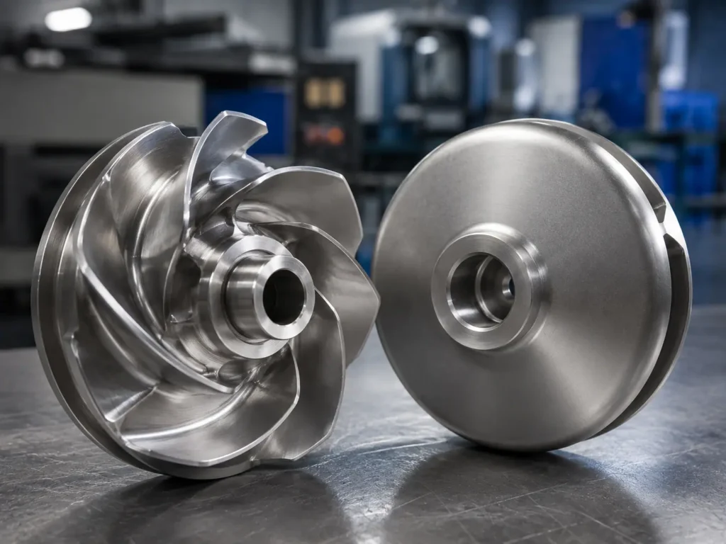
Pump impeller dimensions are the measurements that control how an impeller fits the shaft and casing, how its inlet and outlet geometry matches the pump, and which surfaces must be cast, machined, and inspected. The most important dimensions usually include outside diameter, eye diameter, axial width, bore, keyway, hub diameter, hub height, vane geometry, shroud dimensions, wear-ring interfaces, and specified clearances.
There is no universal pump impeller dimensions chart that can define a correct replacement or custom part from pump size alone. Two impellers with the same outside diameter can have different bores, hub heights, eye diameters, vane profiles, widths, rotation directions, and casing relationships. For manufacturing, the controlled drawing, 3D model, reliable sample measurements, and mating-part information must agree.
Matson manufactures custom industrial pump impellers from drawings, 3D files, physical samples, and specifications. This guide explains which dimensions OEM buyers and sourcing teams should confirm before requesting a quote.
[Image placeholder: Add a real inspection image of a metal centrifugal pump impeller beside a marked drawing, with arrows identifying outside diameter, eye diameter, bore, hub height, axial width, and wear-ring surface. Alt text: “Pump impeller dimensions for custom centrifugal pump impeller inspection”]
Main Pump Impeller Dimensions to Confirm
The drawing should separate functional dimensions from general reference dimensions. A small error in bore size or hub height can prevent assembly. A similar error on a non-functional cast surface may not matter if it remains within the agreed profile and clearance envelope.
| Dimension or feature | Why it matters | What the buyer should provide |
|---|---|---|
| Outside diameter (OD) | Affects casing fit, radial clearance, tip geometry, mass, and the approved hydraulic design. | Finished OD, tolerance, trim status, and whether the sample is worn. |
| Eye or inlet diameter | Controls the suction entrance geometry and relationship to the casing or inlet passage. | Eye diameter, axial location, profile, and inspection reference. |
| Axial width | Affects casing space, shroud position, outlet width, and assembly fit. | Overall width, outlet width where required, and controlling faces. |
| Bore | Controls shaft or sleeve fit and impeller concentricity. | Finished diameter, fit or tolerance, straight or tapered form, datum, and surface finish. |
| Keyway or spline | Transfers torque and controls angular position in many assemblies. | Width, depth, length, location, radius, orientation, and drawing standard. |
| Hub diameter and height | Sets shaft-side fit, axial position, machining access, and mass distribution. | Hub OD, length or height, mounting face, fillet, and mating-part dimensions. |
| Wear-ring or sealing surface | Controls leakage-related clearance and casing or ring fit. | Finished diameter, roundness, runout, surface finish, and mating diameter. |
| Vane geometry | Defines passages and must match the approved pump design. | Vane count, inlet and outlet position, profile sections, angle references, and rotation direction. |
Do not put every dimension under one blanket tolerance. A practical drawing identifies the critical characteristics, datums, inspection method, and acceptance limits for the actual assembly.
Outside Diameter Is Not Enough
Buyers often start with a statement such as “we need a 300 mm impeller.” That is useful for scale, but it is not a manufacturing specification.
For example, two nominal 300 mm centrifugal pump impellers may differ in:
- Closed, semi-open, or open construction
- Single-suction or double-suction inlet arrangement
- Eye diameter and eye profile
- Outlet width and shroud spacing
- Number, curvature, thickness, and axial position of vanes
- Bore, taper, keyway, spline, thread, or other shaft connection
- Hub height and mounting-face location
- Front and back wear-ring surfaces
- Rotation direction and viewing convention
- Final trimmed diameter and balance condition
Outside diameter also needs context. Is it the original design dimension, the finished production dimension, or a worn measurement from an old sample? Has the impeller been trimmed? Are the vane tips damaged or previously ground? Those questions should be answered before a supplier treats OD as a master value.
The custom pump impeller page shows the main pump impeller types and drawing-based manufacturing scope.
Measure the Eye as a Profile, Not Only a Hole
The impeller eye is the inlet area where liquid enters the rotating passage. A single diameter may not describe its full geometry. The eye can include an inlet edge, curved transition, shroud profile, axial location, and relationship to the vane leading edges.
For closed impellers, front and back shrouds may create different reference surfaces. For double-suction impellers, both inlet sides and their symmetry need review. For a worn sample, cavitation, corrosion, abrasive damage, grinding, or rubbing can change the measured edge.
Buyers should provide the eye diameter together with section geometry, datum, axial position, and any critical profile requirement. Matson’s article on the pump impeller eye explains the inlet, damage, sample, casting, and inspection checks in more detail.
Bore, Keyway, and Hub Dimensions Control Assembly
The impeller can look correct and still fail installation because the bore, keyway, hub, or mounting face is wrong.
Confirm:
- Shaft, sleeve, or mating pilot diameter
- Bore type: straight, tapered, threaded, splined, or another approved form
- Fit class or explicit bore tolerance
- Bore length, datum, straightness, roundness, and surface finish when required
- Keyway width, depth, length, end form, and angular orientation
- Hub outside diameter, height, face position, fillet, and shoulder
- Nut, washer, thread, locking, or coupling relationship
- Face and radial runout requirements
Do not copy a scored or enlarged sample bore without checking the shaft or original drawing. Wear can make a loose bore appear to be the design size. Weld repair, bushings, sleeves, and previous machining can also hide the original geometry.
See the impeller hub and bore guide for shaft fit, keyway, mounting face, sample condition, and machining review.
Vane Dimensions Need Clear Reference Locations
Terms such as “vane angle,” “blade height,” or “outlet width” are incomplete unless the drawing defines where and how they are measured.
A curved vane changes direction from inlet to outlet. Its thickness may vary. A cast surface may require a profile tolerance rather than a few isolated caliper readings. Leading edges and trailing edges may have controlled radii, thicknesses, or finishing requirements. On some designs, the 3D model is the main geometry reference while the 2D drawing controls datums, critical sections, tolerances, material, and inspection.
The buyer should identify:
- Vane count and spacing
- Leading-edge and trailing-edge locations
- Vane thickness at defined sections
- Inlet and outlet angle reference conventions
- Passage width and outlet width
- Blade height or shroud spacing at defined positions
- Profile tolerance and inspection sections
- Rotation direction and the side from which it is viewed
The manufacturer should not redraw hydraulic geometry from a few sample measurements unless the engineering owner has approved that scope. Manufacturing review can identify missing or conflicting information, but hydraulic approval remains with the pump OEM or responsible engineer.
Open, Semi-Open, and Closed Impellers Need Different Checks
| Impeller structure | Dimension focus | Common sample risk |
|---|---|---|
| Closed impeller | Both shrouds, eye, outlet width, wear-ring surfaces, bore, hub, axial position, and runout. | Worn ring surfaces, rubbed shrouds, hidden internal passage damage, or incorrect overall width. |
| Semi-open impeller | Back shroud, open-side vane height, wear-plate or casing relationship, back clearance, hub, and bore. | Worn vane tips can reduce height and hide the original open-side clearance. |
| Open impeller | Vane height, front and back geometry, casing or wear-plate relationship, OD, hub, and shaft fit. | Uneven tip wear, bent vanes, grinding, or missing original clearance data. |
| Vortex or recessed impeller | Recess position, casing space, vane envelope, hub, OD, and axial location. | A sample alone may not show the required casing relationship or original recess. |
| Double-suction impeller | Both eyes, central symmetry, dual wear-ring surfaces, overall width, hub or shaft connection, and runout. | Asymmetric wear can make one side an unreliable dimensional master. |
This is why a generic centrifugal pump impeller dimensions chart cannot replace the assembly drawing.
Clearance Is a Relationship Between Parts
Impeller clearance is not always a dimension located entirely on the impeller. It may be the difference between the finished impeller surface and a casing, wear ring, wear plate, cover, or another stationary component.
If a buyer requests a new impeller from a worn sample, the mating part should also be checked. A new wear-ring diameter copied from a damaged impeller may still create excessive clearance against a worn casing ring. Conversely, restoring one side to a nominal value without checking the casing can create rubbing.
For manufacturing, provide the finished impeller dimensions and the mating dimensions or required assembled clearance. The pump OEM or engineering owner should approve the final clearance. Do not use a universal online clearance number for an unknown pump.
How to Dimension a Drawing for Quotation
A useful RFQ package should include a controlled 2D drawing and, for complex geometry, a matching 3D model. Record the drawing number, revision, model filename, units, material, quantity, and which source controls if the files disagree.
At minimum, identify:
- Finished OD and axial width
- Eye diameter and inlet profile
- Bore, keyway, spline, thread, and shaft connection
- Hub dimensions and mounting-face position
- Vane count, direction, and controlled profile sections
- Shroud, outlet, wear-ring, and sealing dimensions
- Datums, tolerances, surface finish, and runout
- Mating-part or required-clearance information
- Material grade and casting, machining, coating, or heat-treatment requirements
- Operating speed and dynamic balancing requirement
- Inspection method and required documents
- Sample condition, including worn, repaired, corroded, rubbed, or balance-corrected areas
Matson’s impeller manufacturing process can include casting, CNC machining, dimensional inspection, material verification, surface treatment, dynamic balancing, and export packing when these requirements are agreed.
Common Questions Buyers Ask
What are the main pump impeller dimensions?
The main dimensions are usually outside diameter, eye diameter, axial and outlet width, bore, keyway, hub diameter, hub height, vane geometry, shroud dimensions, wear-ring surfaces, runout, and equipment-specific clearances.
Is there a standard centrifugal pump impeller dimensions chart?
No universal chart can define a correct custom or replacement impeller. Dimensions depend on the pump design, shaft, casing, inlet, wear rings, impeller structure, approved hydraulic geometry, and manufacturing drawing.
Can a pump impeller be manufactured from outside diameter and bore size?
Normally, no. OD and bore do not define eye geometry, width, hub, keyway, vane profile, rotation, shrouds, wear-ring surfaces, material, tolerances, or balance requirements.
Can Matson copy pump impeller dimensions from a sample?
Matson can review a physical sample for custom manufacturing, but worn, corroded, repaired, bent, rubbed, or previously machined areas must be identified. Critical dimensions may need confirmation from drawings, mating parts, or the equipment owner.
Which dimensions should be inspected first?
Start with functional fit: bore, keyway, hub height, mounting face, OD, axial width, eye, wear-ring interfaces, runout, and specified vane or profile sections. The drawing should state the acceptance criteria and measurement references.
Need a custom pump impeller manufactured from a drawing or sample? Send Matson the controlled drawing, 3D model, sample photos, pump type, material, critical dimensions, mating-part or clearance information, operating speed, balancing requirement, quantity, and inspection needs through the custom pump impeller quote page.